What is Bus Architecture?
Overview
A bus is a collection of electrical pathways or conductors that carry data, addresses, and control signals between different hardware components. These components are linked to the bus, allowing them to interact and collaborate effortlessly, and these all together are called bus architecture. The width (number of data lines), speed, and protocols of bus architectures can vary. A bus's width refers to the number of parallel data lines it contains, which defines how much data can be sent simultaneously. A wider bus offers faster data transfer but may require more physical connections.
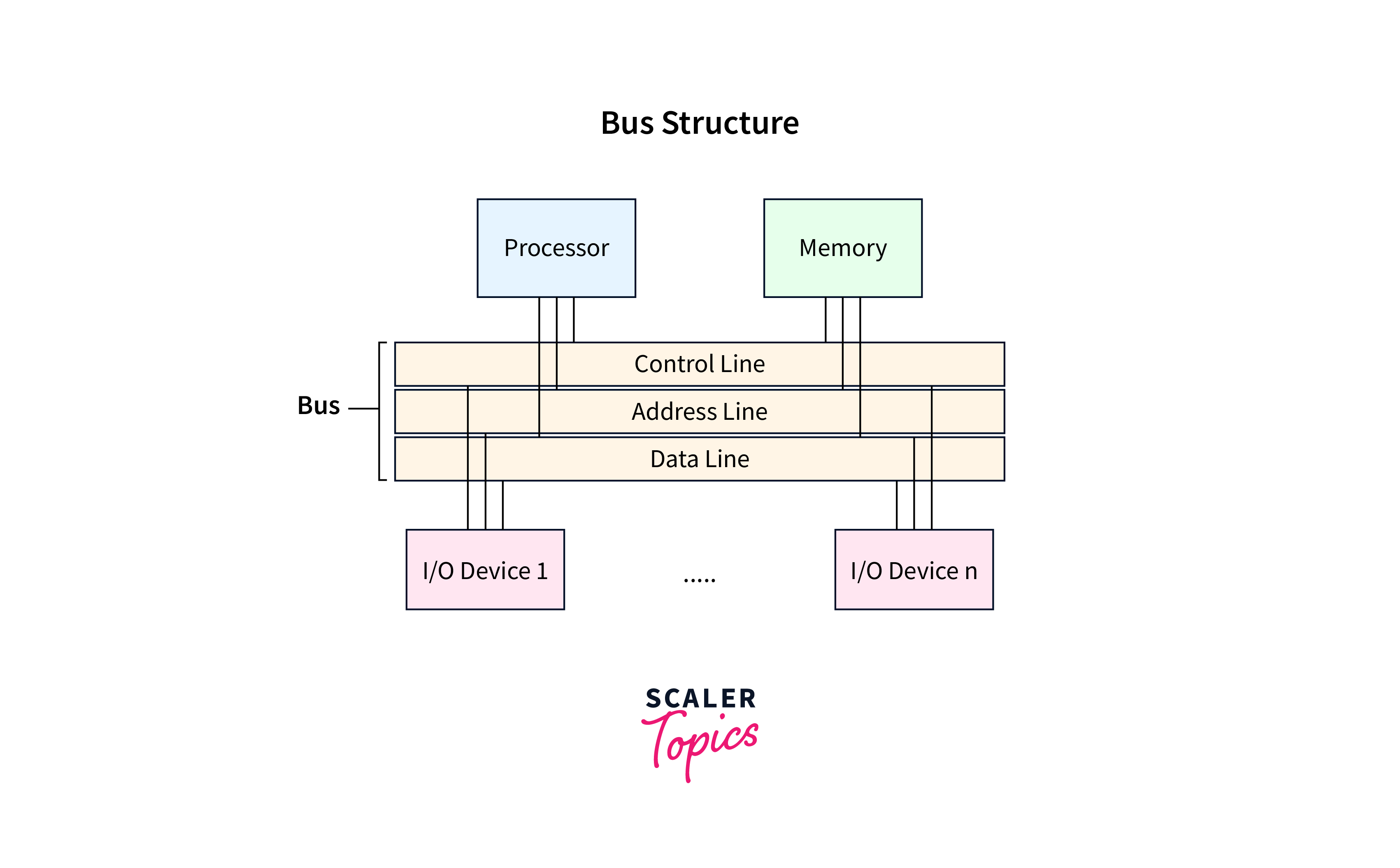
Bus Structure in Computer Architecture
A system bus usually consists of a range of distinct lines, typically numbering from fifty to hundreds. Each line is designated for a specific function, and these lines can be divided into three main functional categories: data lines, address lines, and control lines. Let's discuss each of these in detail.
Scaler Placement Report and Statistics
Scaler learners achieved 2.5x salary growth with average post-Scaler CTC reaching ₹23L.
Data Lines (DL)
- Data Lines (DL) are electrical channels or conductors within a computer's bus architecture that are specifically dedicated to transferring actual data between different computer system components.
- These lines carry binary information in the form of digital signals, such as numbers, instructions, and other data.
- Data lines facilitate parallel data transfer, meaning multiple bits of data can be sent simultaneously.
- The width of the data bus, represented by the number of data lines, determines the quantity of data that can be conveyed in a single operation.
- Each data line can only transmit one bit at a time. For example, a computer system with a 32-bit data bus can transfer 32 bits of data in parallel.
Transform Your Career
Choose from our industry-leading programs designed for career success
Modern Software and AI Engineering Program
Master full-stack development with AI integration

Modern Data Science and ML with specialisation in AI
Advanced data science techniques with AI specialization
Advanced AIML with Specialisation in Agentic AI
Deep dive into AIML with focus on Agentic systems
DevOps, Cloud & AI Platform Engineering
Build and manage AI-powered cloud infrastructure
AI Engineering Advanced Certification by IIT-Roorkee
Premier AI engineering certification from IIT-Roorkee
Address Lines (AL)
- An address line is a collection of electrical channels or conductors within a computer's bus architecture specifically designated to carry memory addresses.
- These lines indicate the source or destination of data during memory read and write operations.
- The number of address lines in the address bus impacts the range of memory addresses that the computer system may access.
- The bus module is determined by the higher-order bits, while the address of memory locations or I/O ports is determined by the lower-order bits.
- When the processor needs to read a word from memory, it simply places the relevant word's address on the address line.
Control Lines (CL)
- In bus architecture, control lines are specific lines that transmit control signals between different computer system components.
- These control signals coordinate and govern the flow of data and instructions between various hardware components, ensuring that actions are carried out in the correct order, and the overall system runs smoothly.
- Control lines act as communication channels for signals that control the behavior of the computer's internal components, such as the central processor unit (CPU), memory modules, input/output devices, and other peripherals.
- These signals are required for memory read and write operations, input/output operations, interrupts, and other control activities.
Some common control signals transmitted through control lines in a computer's bus architecture are as follows:
| Control Signal | Description |
|---|---|
| Memory Write | This command moves the data on the data bus to the addressed memory location. |
| Memory Read | This instruction sends the data from the addressed memory location to the data bus. |
| I/O Read | Enabling this control line sends data from the addressed I/O port to the data bus. |
| I/O Write | When a command is sent over this control line, data from the data bus is sent to the designated I/O port. |
| Bus Request | The activation of this control line signifies that the component has signaled its desire to take control of the bus. |
| Bus Grant | The activation of this control line signifies that the bus has been allocated to the component that made the request. |
| Transfer ACK | This control line indicates that data has been received or placed on the data bus. |
| Interrupt Request | This control line indicates that there are pending interrupts. |
| Interrupt ACK | When the pending interrupt is serviced, this control line acknowledges it. |
| Reset | This control line's bit information initializes all modules. |
Bus Timing
As observed, the control lines of the bus also convey timing details alongside commands. The methods for obtaining timing information via the control line can be classified into two categories:
Turn Learning into Career Growth
Synchronous Bus
- Timing synchronization for all connected devices or components is achieved in the synchronous bus through a control line known as the bus clock.
- This bus clock line transmits a steady stream of alternating 1s and 0s, creating a recurring clock cycle with specific intervals.
- Each clock cycle consists of a single transmission of the sequence 1-0. Any device or component connected to the bus can read this bus clock line.
- Every operation, without exception, starts with the start of a clock cycle. The clock-based synchronization ensures that the transmitting and receiving elements are precisely aligned.
- This steady clock-driven synchronization can achieve continuous data transmission. As a result, the synchronous bus architecture can handle high-speed data transmission.
Asynchronous Bus
- The asynchronous bus configuration does not employ a clock signal to synchronize the transmitter and receiver components. Instead, data transmission is controlled by a handshake protocol between a master and a slave component.
- In this arrangement, the process of data transfer is initiated by the master component.
- It prepares itself for data exchange and signals its readiness by activating the master-ready line. Concurrently, it transmits address and command details across the bus.
- Each connected component then evaluates the address provided on the address line to determine which specific component is being addressed by the master.
- When the addressed component receives the command, it performs the required operation and notifies the processor by activating its slave-ready line. When the slave-ready line is activated, the master relinquishes control of the bus.
- When the addressed component receives the command, it performs the necessary function and alerts the processor by activating its slave-ready line. The master relinquishes control of the bus when the slave-ready line is enabled.
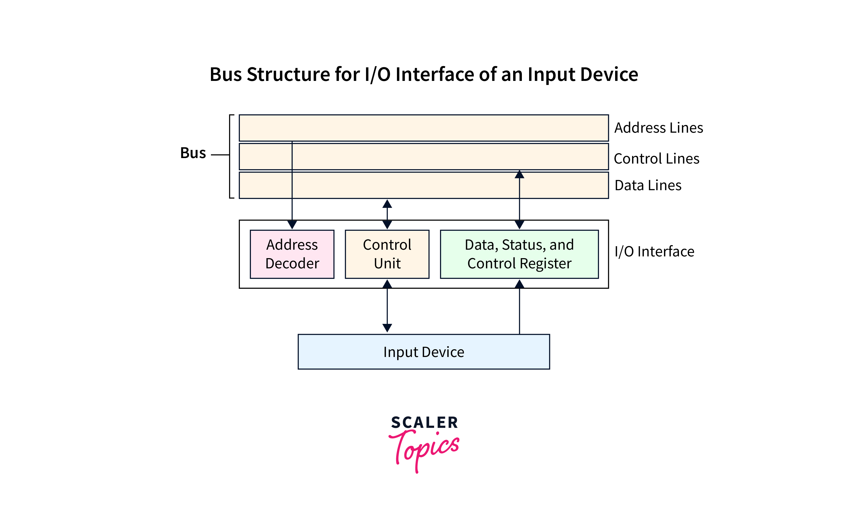
Bus Structure for I/O Interface of an Input Device
Each I/O device interface has a unique set of registers with unique addresses. When the processor writes an address to the bus's address line, all of the bus's devices inspect it. The device that recognizes this address responds to the subsequent control operations transmitted via the bus's control lines.
The processor utilizes the bus's control lines to initiate read/write operations, causing data associated with these operations to be transmitted through the bus's data lines. Consider a keyboard as an example of an input device. The following machine instruction is used when data from the keyboard needs to be transmitted to the processor:
LOAD R2, DATAIN:
The DATAIN, in this instance, denotes the data register connected to the keyboard. This instruction obtains the data stored in the keyboard's DATAIN register and then transfers it to the processor's R2 register.
STORE R2, DATAOUT:
Consider the DATAOUT register to be the data register of a display device. As a result, this instruction will transfer the contents of the processor's register R2 to the display device's data register.
The I/O device interface includes a control register and a status register, which contain information about the I/O device's operations. The interaction of the address decoder, control circuitry, and the interface's registers orchestrates the smooth data transfer to and from the I/O device.
Conclusion
- A bus is a collection of electrical pathways or conductors that carry data, addresses, and control signals between different hardware components.
- The width (number of data lines), speed, and protocols of bus architectures can vary. A bus's width refers to the number of parallel data lines it contains, which defines how much data can be sent simultaneously.
- A system bus usually consists of a range of distinct lines, which can be divided into three main functional categories: data lines, address lines, and control lines.
- Data Lines (DL) are electrical channels or conductors dedicated to transferring data between different computer system components.
- Address lines is a collection of electrical channels or conductors, specifically designated to carry memory addresses.
- Control lines are specific lines that transmit control signals between different computer system components.
- The synchronous bus achieves timing synchronization using the bus clock control line.
- The asynchronous bus configuration does not employ a clock signal to synchronize the transmitter and receiver components.