Decoder in Digital Electronics
What is Decoder in Digital Electronics?
Before we talk about decoders, go and take a quick read of the Scaler article on “Encoders in Digital Logic“. If you’re thorough with encoders, decoders are going to be a child’s play. Why? They’re the complete opposite of encoders!
By definition, Decoder in Digital Electronics convert digital signals to analogue signals. It has n lines as input, and maximum 2n lines as output. Binary decoders give output as high on only one of the output lines depending on the input, and deactivated outputs on every other output line. Complete opposite of the encoder, like I said before!
Here’s a visual representation of how they look like:
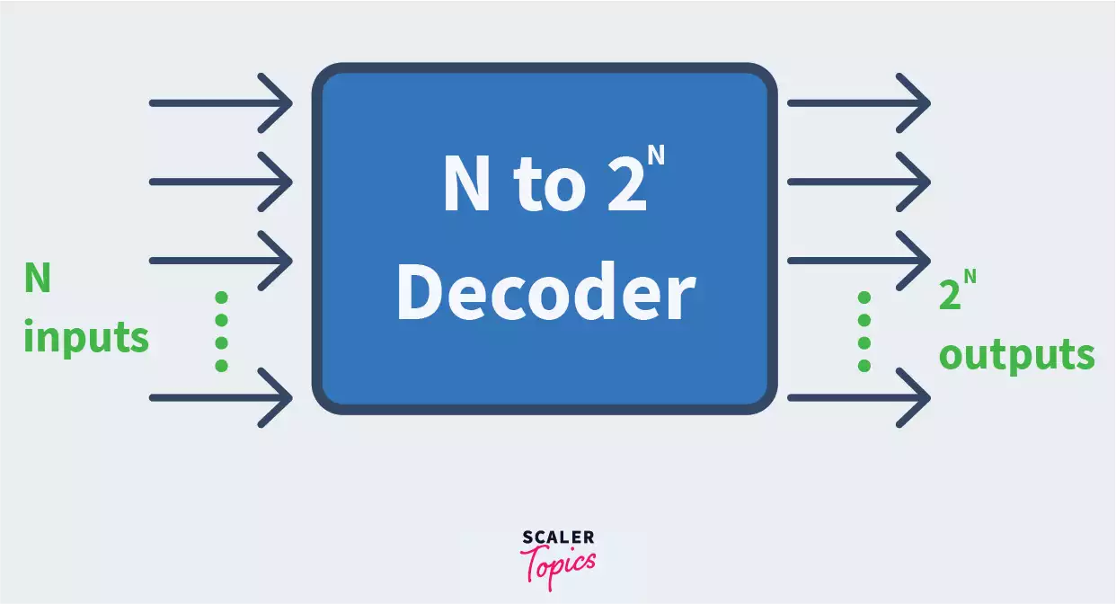
For example, if the input is 1 0 (i.e. 2 in decimal), then the output will be 0 0 1 0. Why do we have 4 bits in the output? Because the number of bits in the output are determined by 2n where n is the number of input lines. Hence the output for 10 will be 0100 which means that the I2 line will be high.
Let us now discuss some prominent kinds of decoders to understand their working better.
Transform Your Career
Choose from our industry-leading programs designed for career success
Modern Software and AI Engineering Program
Master full-stack development with AI integration

Modern Data Science and ML with specialisation in AI
Advanced data science techniques with AI specialization
Advanced AIML with Specialisation in Agentic AI
Deep dive into AIML with focus on Agentic systems
DevOps, Cloud & AI Platform Engineering
Build and manage AI-powered cloud infrastructure
AI Engineering Advanced Certification by IIT-Roorkee
Premier AI engineering certification from IIT-Roorkee
Type I: 2 to 4 line Decoder
A 2 : 4 decoder is the opposite of the 4 : 2 encoder. It has 2 inputs and 4 outputs. If you’ve read our article on encoders, you know how our fingers work.
Basically, we allot 2 states to each finger. Open state = ‘1’ (active High input) or the closed state = ‘0’ (low input).
Let’s say you have 2 fingers open, your job is to detect what they actually mean as in the opposite of what we did in encoders. There, you had to make your input more compact, and here, you have to reverse it, as in make it understandable. Two open fingers means 1 1 i.e. 3 in decimal. So if you had 4 output lines Y0, Y1, Y2, and Y3, you would have represented the input of 1 1 as 0 0 0 1.
Let us now take a look at the truth table for the decoder with inputs as A and B, and outputs as Y0, Y1, Y2 and Y3.
Truth Table:
| INPUT | OUTPUT | ||||
|---|---|---|---|---|---|
| A | B | Y0 | Y1 | Y2 | 0 |
| 0 | 0 | 1 | 0 | 0 | 0 |
| 0 | 1 | 0 | 1 | 0 | 0 |
| 1 | 0 | 0 | 0 | 1 | 0 |
| 1 | 1 | 0 | 0 | 0 | 1 |
Below, we have discussed the logical expressions and circuit diagrams for the 2 to 4 decoder, and to understand them, quickly brush up on some basic digital logic topics such as Logic Gates, SOP (sum of products form) and POS (product of sum). If you do not wish to read them, don’t worry, you have understood the basic idea behind decoders!
From the table above, we can find logical expressions of the output lines in SOP form as:
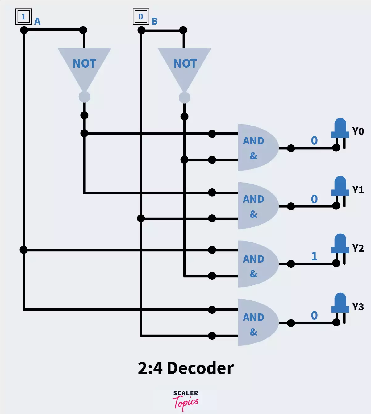
Y0 = A’B’ Y1 = A’B Y2 = AB’ Y3 = AB
These logical expressions can be used to implement the 2 : 4 decoder using gates as follows. Here, A and B are the input lines.
To verify the above circuit diagram, we have taken a set of values from the truth table. We can see that the values given in input to the circuit give us the required outputs.
Type II: 3 to 8 line Decoder
How many possible combinations can you make with just 3 bit inputs? I’m sure you guessed right, 8! (23 = 8)
As the name suggests, we have 3 inputs and 8 outputs in this decoder. We represent the inputs using A, B, C and the outputs using Y0, Y1, Y2, Y3 ,Y4 ,Y5, Y6, Y7.
After studying encoders, and the basic idea behind decoders, I’m sure you can write down the truth table for the 3 to 8 decoders. Make sure that each set of inputs will only have one output line with a high input.
If you’ve made the truth table correctly, the logical expressions for the output lines should look like this:
Y0 = A’B’C’
Y1 = A’B’C
Y2 = A’BC’
Y3 = A’BC
Y4 = AB’C’
Y5 = AB’C
Y6 = ABC’
Y7 = ABC
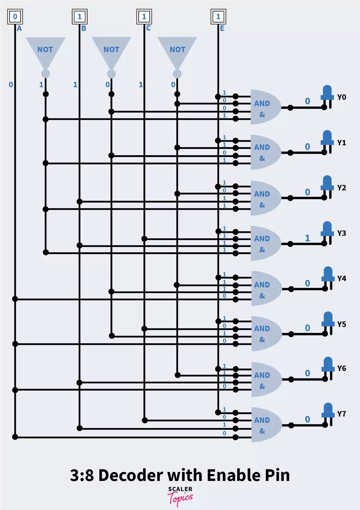
Using the above we can make a logic circuit diagram as follows. We have also added one set of input values so verify the circuit diagram:
(1, 0, 1) = (0, 0, 0, 0, 0, 1, 0, 0)
What if you wanted to switch off this decoder for some reason?
Something to observe in the above logic circuit diagram is that all output lines are resultant of an AND gate, which means, for any output to be active High, all values entering that AND gate must be ‘1’. If we add a ‘0’ to any of these, wouldn’t the AND gate give a ‘low’ output? That is the whole idea behind the switch for the decoder.
We add an ‘enable’ pin to all the AND gates of the decoder. To switch off the decoder, we can simply ground the enable pin.
In the logic circuit implementation of the decoder the line labelled ‘E’ is the enable pin.
Type III: 4 to 16 line Decoder
Again, as all other encoders and decoders discussed above, this decoder has 4 inputs and 16 outputs. The previous decoder discussed was 3 : 8. Do you think that could be used for designing the 4 : 16 decoder?
Absolutely, yes. We are going to design the 4 : 16 decoder using two 3 : 8 decoders. The output lines would be 8 + 8 = 16, as required. But what are we going to do about the 3 + 3 = 6 input lines? We need just 4!
Remember the enable pin used for switching on and off the decoder? That is the fourth pin that would help us in making the 4 : 16 decoder, the rest of the 3 input lines will be the same. Let us understand it better by seeing the logic circuit diagram.
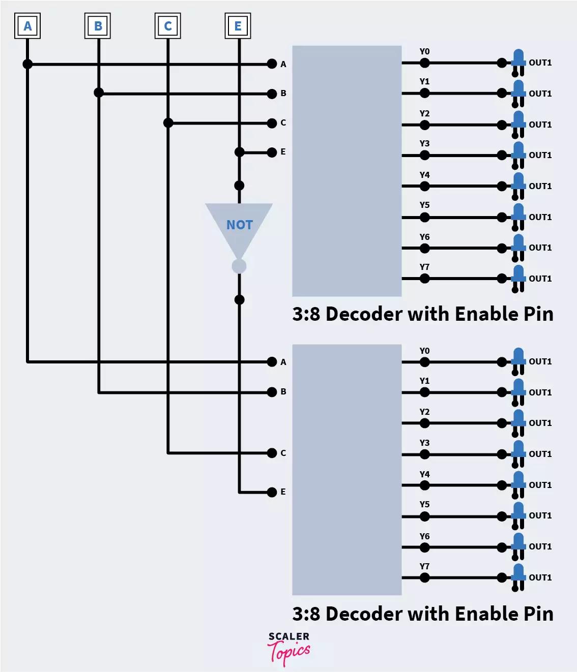
Complicated huh? We’re going to leave it up to you to design the truth table and logical expressions for output lines of the 4 : 16 decoder to test your learning!
Uses of Decoders
-
Decoders are used when we need to input data to a specific output line. The most common application of this is in addressing core memory in a computer, where we have a specified memory location to store the input data.
-
They are used in code conversions like binary to decimal, like the 2 to 4 decoder.
-
It is used in data distribution as in de-multiplexing (combining multiple input streams to one)
Conclusion
-
Decoders are combinational circuits implemented with the help of logic gates.
-
The main idea behind using encoders is to save space occupied by data and reduce the number of wires required to implement circuits.
-
Encoders have maximum 2n input lines and n output lines.
-
Types of Encoders discussed:
- 4 : 2
- 8 : 3 (octal to binary)
- Decimal to BCD
- Priority Encoder
-
Priority encoder solves the problem of ambiguity when all inputs are low, and also the main problem of more than one active High inputs in encoders.