ER Diagram In DBMS

For making an ER diagram, we need to first identify the different fields/entities that should be present in a database, the attributes that describe these entities, and the type of relationship that exist between them.
All this information is collected and formulated in the form of a diagram known as an entity-relationship diagram (ERD). Therefore, this ER diagram is a logical view of the database and describes the structure of the database.
What is an ER Diagram in DBMS?
An Entity Relationship Diagram in DBMS is a blueprint of the database that can be later implemented as an actual database in the form of tables. It is a "diagrammatic representation of the database".
An ER diagram is used for creating a systematic study of the data requirements and then making a proper database. It is considered to be one of the best practices before implementing an actual database.
An ER diagram is made up of three components, an entity, its attributes that describe the entities such as the color, and price are some of the attributes of a Car entity, and the relationship that exists between these entities. These ER diagrams are used to show the relationships among various entities in a database.
At first, the entity-relationship diagram might look close to a flowchart, however, they contain some set of symbols and notations and their meanings are what make them unique.
Transform Your Career
Choose from our industry-leading programs designed for career success
Modern Software and AI Engineering Program
Master full-stack development with AI integration

Modern Data Science and ML with specialisation in AI
Advanced data science techniques with AI specialization
Advanced AIML with Specialisation in Agentic AI
Deep dive into AIML with focus on Agentic systems
DevOps, Cloud & AI Platform Engineering
Build and manage AI-powered cloud infrastructure
AI Engineering Advanced Certification by IIT-Roorkee
Premier AI engineering certification from IIT-Roorkee
A Simple ER Diagram
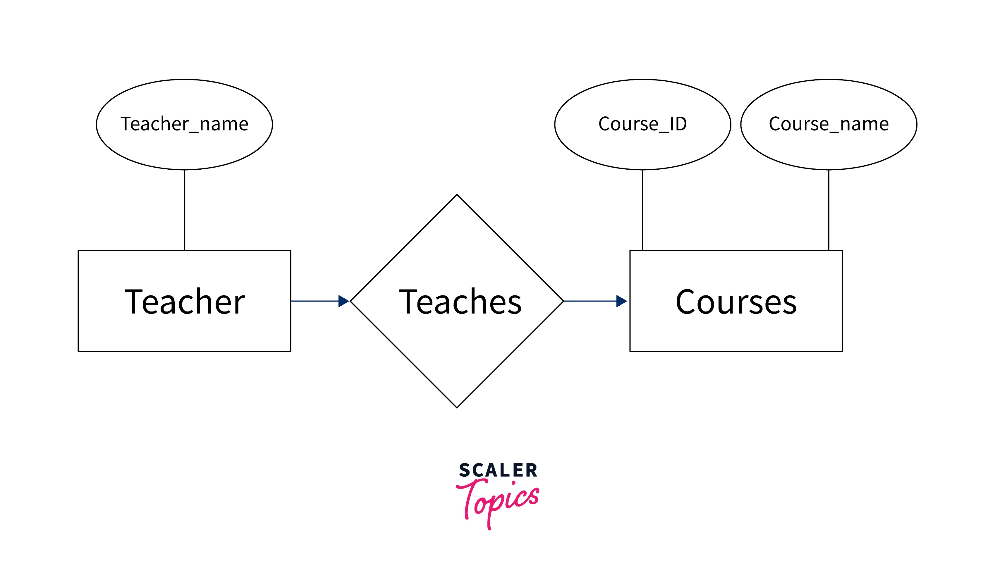
In the above diagram, Teacher and Courses are two entities whereas teacher_Name is the attribute of the entity teacher. Similarly, the Course_ID and Course_name are the attributes of the entity Courses.
Moreover, the relationship between the two entities will be many to many since many teachers can teach many courses at a University. Therefore, all the necessary components, that is, entities, attributes, and the relationship between the entities have been specified in the above entity relationship diagram.
However, the above entity-relationship diagram is made of many symbols and notations which will be discussed in the subsequent topics of this article.
Why Use ER Diagrams?
The main reasons for using the ER diagram before constructing an actual database are as follows:
- An Entity Relationship Diagram is used for modeling the data that will be stored in a database.
- The database designers get a better understanding of the information that will be contained in the database using the Entity Relationship Diagram.
- An ER diagram is used as a blueprint by the database designers to implement the data in a certain application.
- They define what data will be stored in the databases, that is, the entities and their attributes.
- However, they also specify the relationships between the data.
- It provides a preview of how the tables should be connected and what entities are in which table.
- These ER diagrams can easily be converted into relational tables that help in the designing of the software quickly.
ER Diagrams Symbols & Notations
Since we know the entity-relationship diagram has entities, attributes, and the relationship between the data. However, all these components of the ER diagram are represented with the help of certain symbols. Three symbols are used to make an ER diagram, which are, rectangle, oval, and diamond.
However, all other symbols that are used to make an ER diagram are sub-elements and are based on the main elements of the ER diagram.
Let us discuss each symbol and its usage in an ER diagram:
- Rectangle:
It is used to represent the entities in an entity-relationship diagram. - Ellipses/Oval:
This symbol is used to represent the attributes in an entity-relationship diagram. - Diamond:
This symbol is used to represent the type of relationship that exists between the entities such as one-to-one, many-to-one, and many-to-many. - Lines:
It links the entities to the relationship types whereas the attributes to the entity types. - Double Ellipses:
It is used to represent a multivalued attribute. - Double rectangle:
It is used to represent a weak entity. - Double diamond:
It is used to represent a weak relationship between entities.

Components of the ER Diagram
This ER diagram is made up of three components:
- Entity
- Attributes
- Relationships
Let us discuss each of these components in detail:
-
Entity:
An entity is any real-world object that can either have physical existence or a simple fact or any event that happens in the real world. It can be anything that stores data in the database. However, these entities consist of some attributes which describe the entity. There are two types of entities namely strong and weak entities. The weak entities are the ones that are not completely identified by their attributes and rely on the relationship with some other entity. However, strong entities are completely identified by their attributes.
Example : Student enrolls in courses. In this, the Students and courses are entities. Also, every student is identified by a unique ID, the student_id therefore, it comes under the category of a strong entity whereas a room can only exist if there is a building therefore, the room is considered to be a weak entity concerning the building. -
Attributes:
Attributes are the properties that define an entity in an entity-relationship diagram. It is represented by an ellipse/oval in the ER diagram.There are four categories in which the attributes can be distributed:
- Key attribute:
This attribute can uniquely identify an entity in an entity set. For example, the Aadhar number is a key attribute that can identify a person. - Composite attribute:
It is a combination of other attributes in an ER diagram or, in other words, the attributes that can be divided into sub-attributes or sub-parts are known as the composite attributes in an ER diagram. For example, the address field in a table is a combination of the state, city, Pin, and street attributes. - Multivalued attribute:
It is an attribute that can hold multiple values. For example, a person can have multiple phone numbers. - Derived attribute:
These attributes are derived from other attributes in a database. An example of a derived attribute can be the age of an employee which must be derived from the Date of Birth of that employee.
- Key attribute:
-
Relationships:
This component is used to define the relationship that exists between different entities in an ER diagram. It is represented by a diamond shape. Three types of relationships exist between the entities that are as follows:- One-to-One:
In this type of relationship, a single instance of an entity is associated with a single instance of another entity.
For example : A person has an Aadhar card. - Many-to-One:
When many instances of an entity are associated with a single instance of another entity then it is called a many-to-one relationship.
For example : Employees are working on a project, therefore, many employees are working on a single project. - Many-to-Many:
When many instances of an entity are associated with many instances of another entity, then it is known as a many-to-many relationship.
For example : Teacher teaches the courses.
- One-to-One:
Best Practices
- You must take care that one entity should appear only once in the ER diagram.
- Eliminate the redundant entities or relationships from the entity-relationship diagram.
- You should never connect relationships.
- You should use color coding to highlight the important points in an ER diagram to make it more understandable and clear.
- You should follow a naming convention for each of the entities, attributes, and relationships that are present in the entity-relationship diagram.
- You must ensure that the ER diagram supports all the data that needs to be stored in a database.
Conclusion
- An ER diagram is a logical view of a database.
- An ER diagram is the structure of a database before it is implemented.
- The three basic symbols that are used to make an entity-relationship diagram are rectangle, oval, and diamond. However, all the other sub-elements can be derived from the main symbols.
- The three main components of an ER diagram are an entity, attribute, and relationship.
- An entity is a real-world object that is either recognizable or non-recognizable.
- The attributes are the properties that are used to describe an entity.
- It is very helpful to the database designers as they get a clear idea about what is to be stored, how it is to be stored, and how to connect the different entities in a database.