Difference Between Half Adder and Full Adder
Prologue
Welcome! Today we will be discussing half-adders, full-adders, their use, their differences, and much more!
Introduction
I know we have thrown the terms here and there quite a few times. But what do these terms actually mean? Adder for what? Apples, or bananas, or maybe horses? What is there to add?
Adder is a combination circuit which is used to add 2 binary digits, or bits. More specifically, this is what a half-adder does, that is, add two bits. So let’s go ahead and build the logic and intuition behind the half adder, see where it falls short, and why do we need a full adder at all?
Basic and Not So Basic Concept of Addition
(Note: If you’re familiar with base-2 number system addition, then you can skip this part)
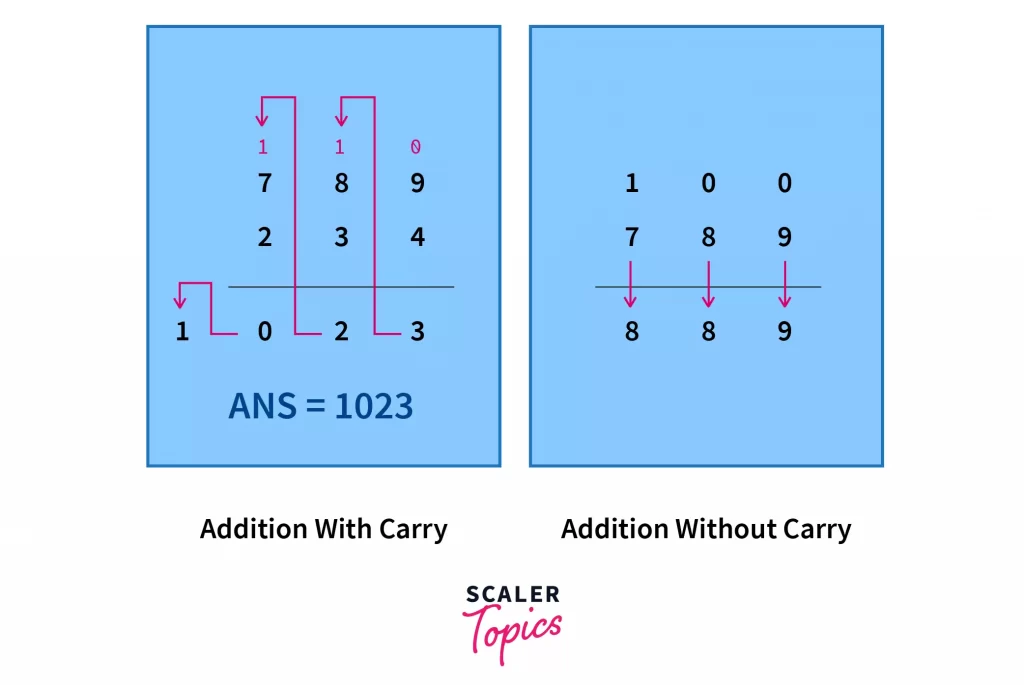
Let’s begin with thinking of the process of addition the way we are taught in junior classes. We have two multiple digit numbers, and we stack them one below the other and then add them digit by digit from right to left.
While performing the addition of digits, we take the two digits, we add them. Let the result be K. Now K could be a one digit or two digit number in itself.
1. If K is a one digit number, we copy it to our sum as it is, and move on to the next digits on the left.
2. Otherwise, we copy the one’s place digit of K in the sum, and carry over the tens place digit to the next digit sum on the left. If you think a little creatively, the above case when K is a one digit number is a special case when the carry = 0.
Notice that all this was done in the base 10 number system. In digital logic, we deal with the base-2 number system. So is there a way we can transform the above described process into one that performs base-2 addition. Let’s see.
Let’s keep analysing with our K. So first question, why did we need a carry, or why couldn’t we write the two digit sum as it is? Because in any base B number system, we have at most B distinct symbols to represent numbers. All numbers equal to or greater than B must be written as a combination of the different symbols we have.
So when B = 10, we have only 10 symbols: 0, 1, 2, 3, 4, 5, 6, 7, 8, 9. All numbers greater than 10 are written as combinations of these symbols, eg, 12, 34 etc. When B = 2, our symbols are 0 and 1. When B = 16, we have 16 different symbols! They are 0, 1, 2, 3, 4, 5, 6, 7, 8, 9, A, B, C, D, E, F. All numbers greater than 16 are represented as combinations of these symbols.
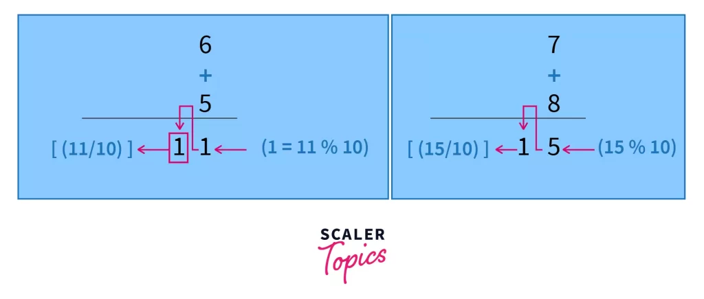
So in addition, whenever our K is greater than 10 (or say B), we need a carry. What is this carry? And what is the number we write down in the sum before moving forward. Try to think before moving forward. (Hint: try adding 9, 19, 8, or more numbers and observe the pattern)
Answer: The carry is floor(K/10), or what programmers refer to as “integer division”. Let’s see how this fits. And the number we write down in the sum before moving forward with the carry is (K mod10) or (K%10)
When K = 9+8 = 17, our carry is floor(17/10) = floor(1.7) = 1
The number we write down in the sum (the ones place digit of K) = 17 mod10 = 7
This concept extends to any base B and any count of numbers you add. Suppose you add 3 numbers in base 10, say 9+8+7+6, you get K = 30. Now your carry is 3 and the digit you write down is 0.
Take another example, say base 16. You add some numbers, say 9+A+F = 9+10+15 = 34 (in base 10). So you first write down 34mod16 = 2, which becomes your unit digit, and you write down carry which is floor(34/16) = 2 which becomes your carry. So your answer then becomes 22 (in base 16).
The Bit Addition and Half-Adder Theory
Now we will apply the concepts we learned in the last section on binary digits. Let’s make a table to keep track of our results. We have two bits as input, A and B. Our outputs are Sum and Carry
| A | B | S (Sum Bit = (A+B)%2) | C (Carry = (A+B)/2) |
|---|---|---|---|
| 0 | 0 | 0 | 0 |
| 0 | 1 | 1 | 0 |
| 1 | 0 | 1 | 0 |
| 1 | 1 | 0 | 1 |
Now our task is to implement such a circuit using logic gates that outputs S and C according to the table we have formulated above. In digital logic, this is the principle we always use to design circuits.
- Identify the input(s)
- Identify the output(s)
- Make all possible inputs (from 0…000 to 1…111, depending on how many inputs are there) and construct a truth table
- Remove rows corresponding to wrong inputs (the one which are not req in the given case)
- Formulate logical equations (or boolean equations, using observation, KMap, or Quinn McClusky Table method)
- Design a circuit using those equations
Now let’s analyze the table we have formulated above. Notice that the column S is 1 only when exactly one of either A or B is one. Otherwise it is 0. Do you remember which boolean or logical operation behaves in this fashion? The XOR operation, of course. And the carry bit is 1 only when both A and B are 1, and this operation is, of course, the logical AND operation.
A⊕B (or XOR operation of 2 boolean variables or bits A, B) is defined as AB’+A’B, where X’ denotes the complement of X.
The truth table for XOR operation is as follows for a quick recap:
| A | B | A⊕B |
|---|---|---|
| 0 | 0 | 0 |
| 0 | 1 | 1 |
| 1 | 0 | 1 |
| 1 | 1 | 0 |
So now we have our boolean or logical equations for adding two bits. Let’s recapitulate and see what they are. On adding two bits A and B, I get
- First bit, which is A⊕B
- The carry bit, which is A ∙ B ( where ∙ operation is logical AND operation)
Using these two equations we will be designing a half adder as follows:
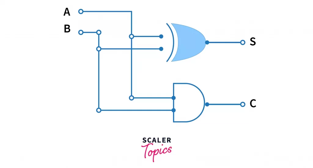
Voila! We’ve successfully designed a half adder, which adds two binary digits, A and B and outputs their sum, S, and a carry C. When C = 0, we can ignore it, but if it is not, then we simply write C in front of S, and that is our total sum.
E.g. A = 1, B = 1. A+B should give the binary equivalent of 2, that is 10
Let’s see. S = A⊕B = 0 and C = AB = 1. Since C !=0, we append C in front of S, and our final result is 10, which is the binary equivalent of 2. Now we’ve also seen how our half adder works!
Where Does Half Adder Fall Short?
For a very simple illustration consider a situation when we want to add two binary numbers having at least two or more bits, e.g., A = 11, B = 10. How should we proceed?
One very logical scheme which comes to mind at first is to cascade 2 half adders. Now this block of cascaded half adders will take input and will spit out the sum. Let’s see how it goes.
Let us represent A = A₁A₀ and B = B₁B₀. Now our cascaded half adders look like:
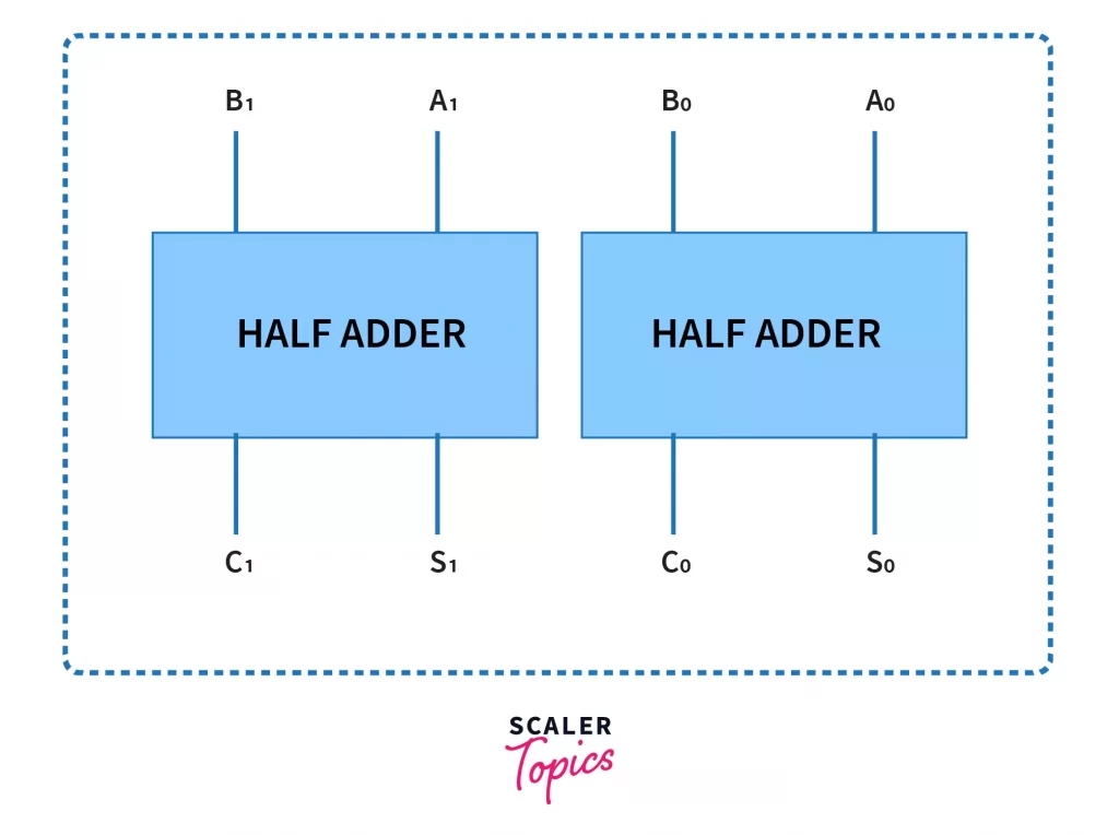
Let’s see what our output is when A = 11 and B = 10. Theoretically, A+B = 5 (in base 10) = 101 (in base 2).
Let’s observe our outputs at the terminals S₀, C₀, S₁, C₁. These are 1, 0, 0, 1 respectively. Well, clearly it doesn’t match our required output. I believe it’s quite clear what went wrong here. Can you guess it? Pause for a moment before moving forward.
Answer: The carry C₀ should not be the part of the output. It should go to the next half adder as part of the input, like normal addition works. At every digit addition, we check if there is a carry from the previous addition and if yes, then we add it to the current sum.
So we need an adder which outputs the same things as a half adder does, that is, the current sum bit and a carry bit, and each adder in the cascaded system should be able to accept the carry as input. That’s why we need a full adder.
Full Adder
Carrying our conclusions from the last section, we see that the half adder was not able to perform multi-bit addition. Of course, we could choose to ignore the in-between carry results if they are all zero, and our result would be correct, even with the cascaded half adders. But the carry is not always 0. We need to come up with a better combinational circuit which can take the carry from the previous bit addition into account. So that’s why we have a full adder. Let’s see what a full adder does:
- It takes three inputs (unlike half adder, which took only two inputs) A, B, the current bits to be added, and Cin, the carry resulting from the previous bit addition on the right hand side of the number.
- Cascading full adders together will result in a binary adder, which can perform additions of numbers in binary form. So going by the information we have for the desired combinational circuit of full adder, we can proceed to design it.
Input: A, B, Cin
Output: S, Cout
| A | B | Cin | S ((A+B+C)%2) | Coutfloor ((A+B+C)/2)) |
|---|---|---|---|---|
| 0 | 0 | 0 | 0 | 0 |
| 0 | 0 | 1 | 1 | 0 |
| 0 | 1 | 0 | 1 | 0 |
| 0 | 1 | 1 | 0 | 1 |
| 1 | 0 | 0 | 1 | 0 |
| 1 | 0 | 1 | 0 | 1 |
| 1 | 1 | 0 | 0 | 1 |
| 1 | 1 | 1 | 1 | 1 |
Now that we have out truth table, using any minimization method, we can find the minimized expression/equations for our two outputs:
As you might have noticed, there are two minimized forms for Cout. Although the first one seems simple, it uses more gates. The first one uses 3 AND gates + 3 OR gates while the second one uses 2 AND gates + 1 OR gate + 1 XOR gate.
So while drawing the circuit we will be using the second minimized form. Let’s look the circuit diagram now:
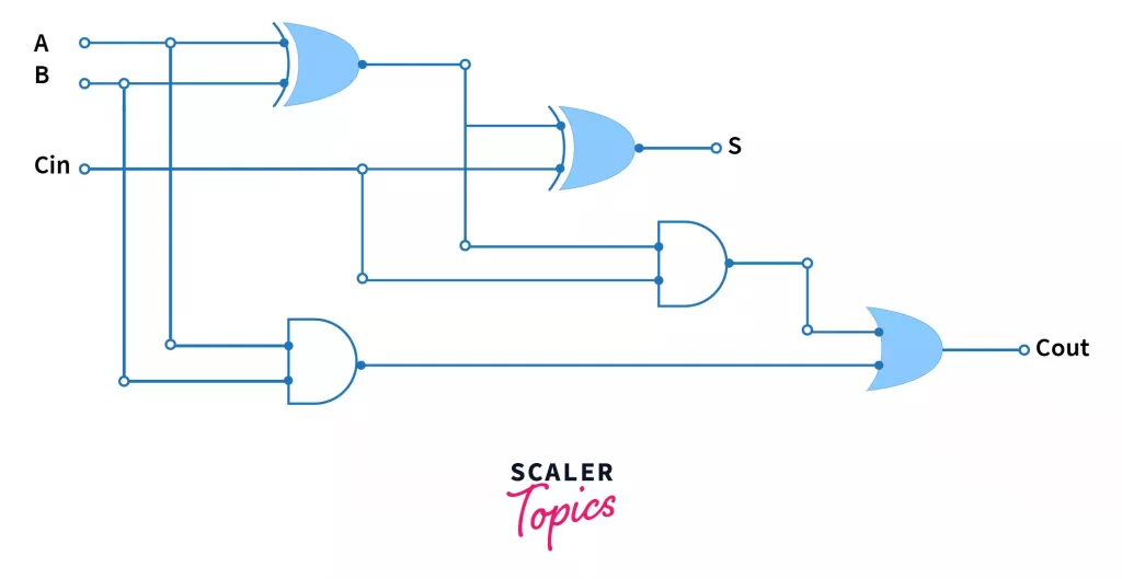
As you can see, using the second form has one more advantage that we can use the XOR operation in calculating both the sum bit S and the output carry Cout. Thus we need only 5 gates to implement a full adder circuit.
Now let’s see how this circuit helps us in solving the problem caused by the cascaded half adder. Again, we will be taking the same example. Where A = 11, B = 10. This time again, we will try cascading two full adders together, but this time, we will connect the carry output of the rightmost full adder to the input-carry of the leftmost full adder.
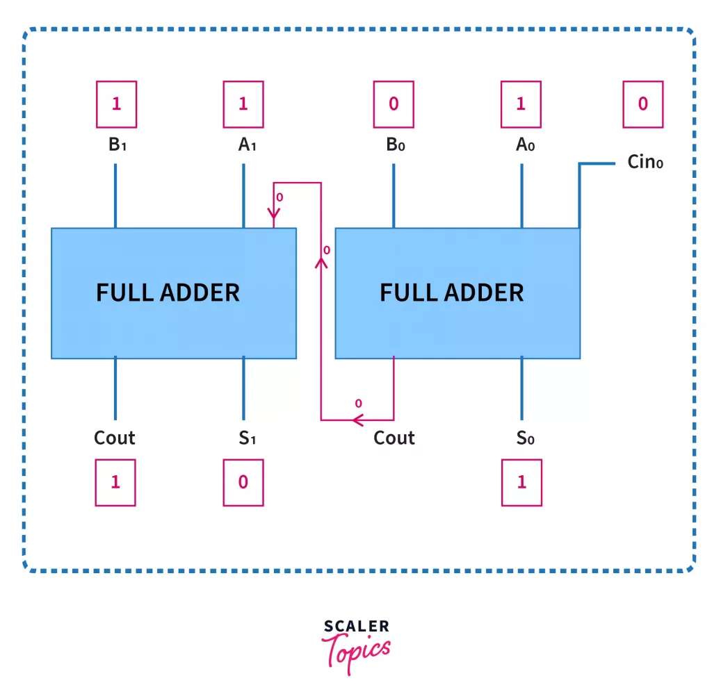
As you can see here, we have set initial input-carry = 0, because for the initial bits there was no carry to begin with. The example inputs and corresponding outputs are written in red boxes, and we can verify that the final answer is (beginning from left) is 101.
So we see that the full adder is a much more powerful adder than the half adder, not only because it can add 3 bits, but also because cascaded full adders allow us to perform binary addition for numbers in which at least one of the numbers has more than 1 bits in its binary representation.
For example, let us have a look at a 4-bit binary adder constructed with 4 cascaded full adders.
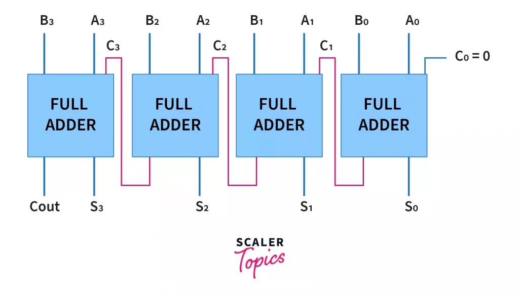
Notice that here too, we’ve set the initial input carry as 0. Just for clarity, this binary adder adds the numbers A (with binary representation A3A2A1A0) and B (B3B2B1B0) and gives output Cout S3 S2 S1 S0. Of course, we can choose to ignore the Cout bit if it is 0, but that is the job of the software which is reading the output to ignore leading zeros.
Also, we could have used a half adder in place of a full adder in the rightmost position, because there is no carry bit before that. But using a similar design repeatedly is often more feasible from a manufacturing point of view.
I would like the reader to understand that it is not necessary that both or any of the numbers being added up using this adder (drawn above) are of 4 bits. For example we can add a 2 bit+3 bit, a 4 bit+ 1 bit number pair , or even a 4 bit+4 bit number pair. If there are less than 4 bits. We just pre-append 0s to the number which has a lesser number of bits than the adder. For example, in the above adder, 110 and 11 will be added as 0110 and 0011 respectively.
Important: The added implement above using full adders is technically called Ripple Carry Adder, because the carry propagates from the rightmost side to left most side sequentially. What this essentially implies is that the leftmost full adder will have to wait for all previous full adders to complete their execution so that it can generate the correct output using the correct carry it receives from the previous full adder. This sequential flow of carry information from right to left causes propagation delay in ripple carry adder.
To counteract this, we use carry look ahead adder, which computes carry bits without waiting for previous stages’ carry inputs to be propagated. The carry bits for all stages are precomputed at once, as soon as the input is provided to the binary adder. Further discussing carry look ahead adder is out of scope of this article, so interested readers are encouraged to learn more about it from books and online resources.
Difference Between Half Adder and Full Adder
Let us summarize the various points we have learnt about half adder and full adder using a table which highlights the differences between them for each considerable parameter.
| HALF ADDER | FULL ADDER |
|---|---|
| Takes 2 inputs, A and B, thus is capable of adding only 2 bits at once. | Takes 3 inputs, A, B, C, thus making it capable of adding 3 bits at once. The third input is often given as the carry input from the previous addition step. |
| Cascaded half adders cannot add multi-bit binary numbers | Cascaded full adders are capable of adding multi-bit binary numbers, and thus are used in designing binary adders. |
| The sum bit expression isS = A⊕B | The sum bit expression isS = A⊕B⊕C |
| The output-carry bit expression isC = AB | The output carry bit expression isC = AB+BC+AC = AB+C(A⊕B) |
| Only AND and XOR gates are required to implement half adder circuit | The gates required to implement full adder circuit are AND, OR, and XOR gates |
| The minimum number of gates required are 2 (1 XOR + 1 AND) | The minimum number of gates required to implement full adder circuit are 5 (2 XOR + 2 AND + 1 OR) |
 |  |
Although it is interesting to note a few similarities both of these adders possess:
- They are combinational circuits, that is, they are not sequential
- Both of them produce exactly one two outputs
- Both of these circuits can be implemented using only NAND and NOR gates (see Wikipedia link below)