Drawing UML diagrams
Overview
A class diagram is a blueprint for creating objects. The Unified Modeling Language (UML) is a powerful language for visualizing the design of a system or object. Before creating a prototype, a UML diagram is ideal for designing a product and focusing on crucial details such as ergonomic design. It is also a significant aspect of project documentation. A budding software engineer can learn the skill of drawing UML diagrams online using various tools available.
What is a Class Diagram?
A class diagram is a static structure used in software development. A class diagram depicts the classes, properties, operations, and relationships. This aids software engineers in the development of application code. It is also used to describe, visualize, and document various aspects of a system.
The only UML diagrams that can be transferred directly to object-oriented languages are class diagrams. As a result, they are often utilized in the modeling of object-oriented systems and the development of object-oriented systems.
Transform Your Career
Choose from our industry-leading programs designed for career success
Modern Software and AI Engineering Program
Master full-stack development with AI integration

Modern Data Science and ML with specialisation in AI
Advanced data science techniques with AI specialization
Advanced AIML with Specialisation in Agentic AI
Deep dive into AIML with focus on Agentic systems
DevOps, Cloud & AI Platform Engineering
Build and manage AI-powered cloud infrastructure
AI Engineering Advanced Certification by IIT-Roorkee
Premier AI engineering certification from IIT-Roorkee
Class Notation
As seen above, the class is represented by a single rectangle. Class Name is located at the top of the rectangle, followed by Attributes in the middle and Operations at the bottom.
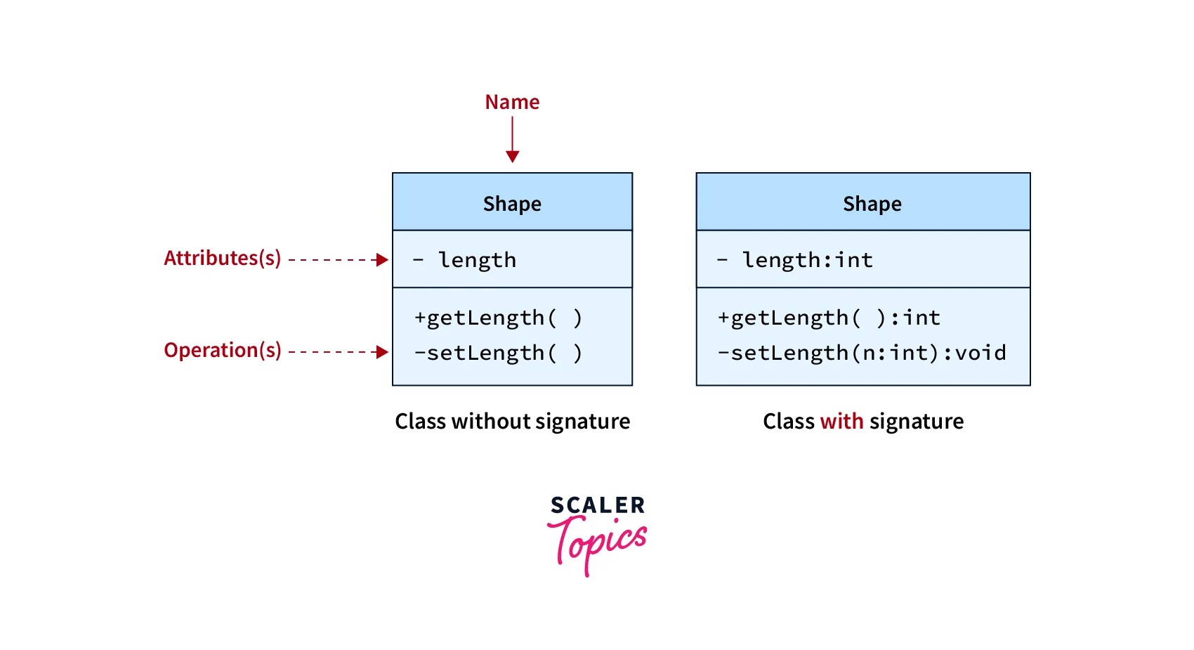
Class Name
For graphical representation, the class name is critical. It should be written in bold and begin with a capital letter in the top compartment. Moreover, an abstract class should also be written in italics.
Attributes
All of the qualities of the modeled item are listed under attributes, which are written in the middle compartment. You can easily add new properties or derive new attributes from existing ones. Attributes must be meaningful and are typically used in conjunction with the visibility factor, which describes an attribute's accessibility.
Turn Learning into Career Growth
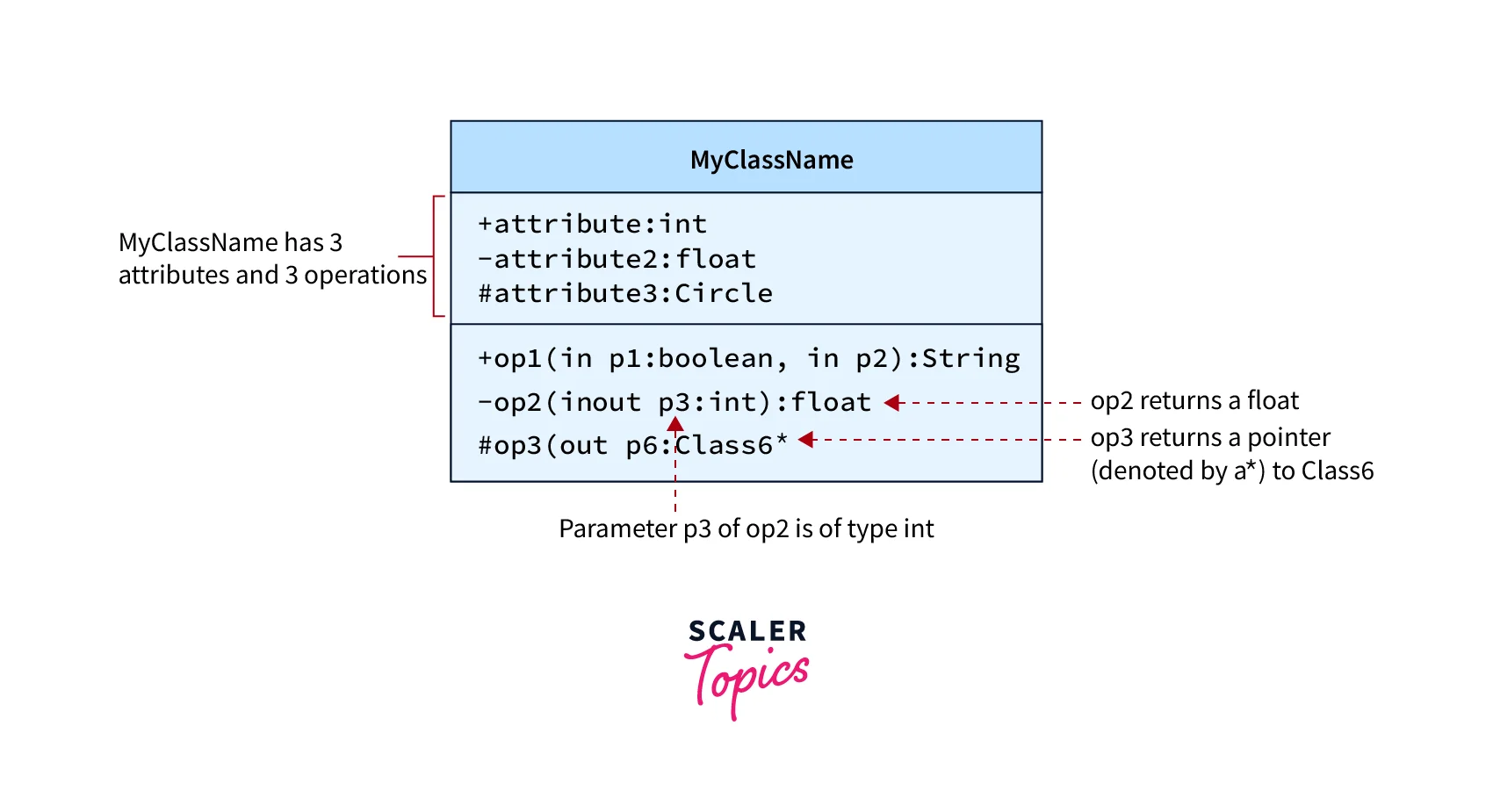
Operations
Operations are processes that a class knows how to perform. They correspond to a class's methods. You don't need to show operations that are similar to attributes because that information is already implied.
Scaler Placement Report and Statistics
Scaler learners achieved 2.5x salary growth with average post-Scaler CTC reaching ₹23L.
Visibility
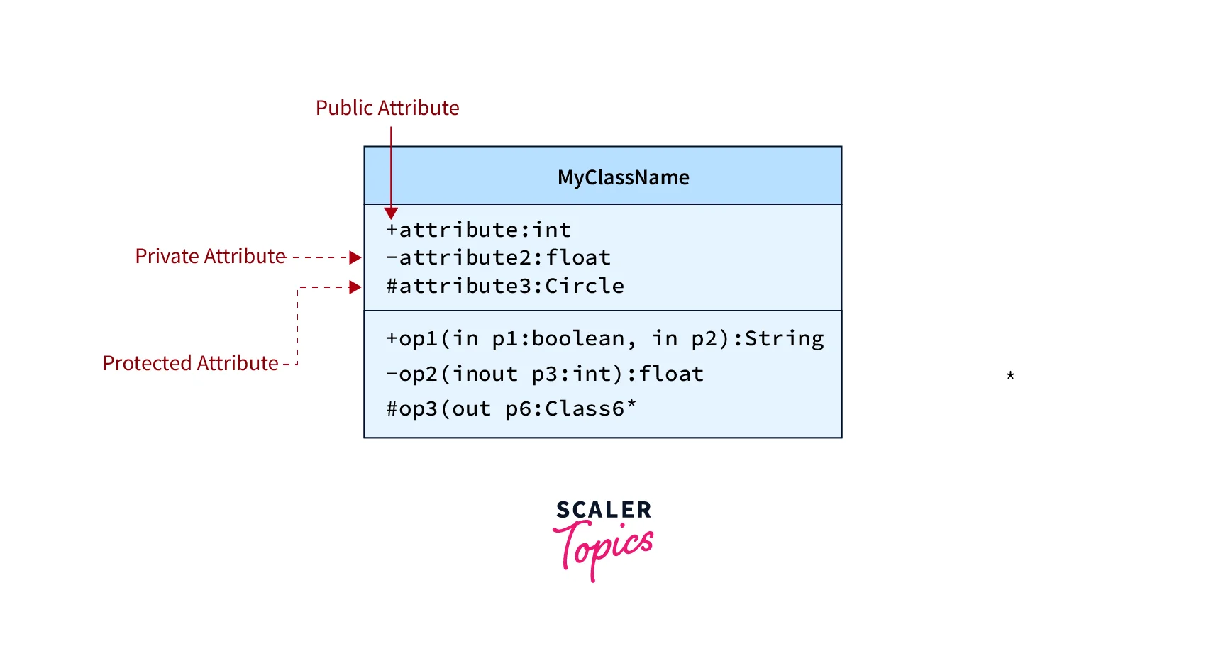
In a class, the +, -, and # symbols preceding an attribute and operation name indicate their visibility. \+ denotes public attributes or operations \- denotes private attributes or operations \# denotes protected attributes or operations
Relationships
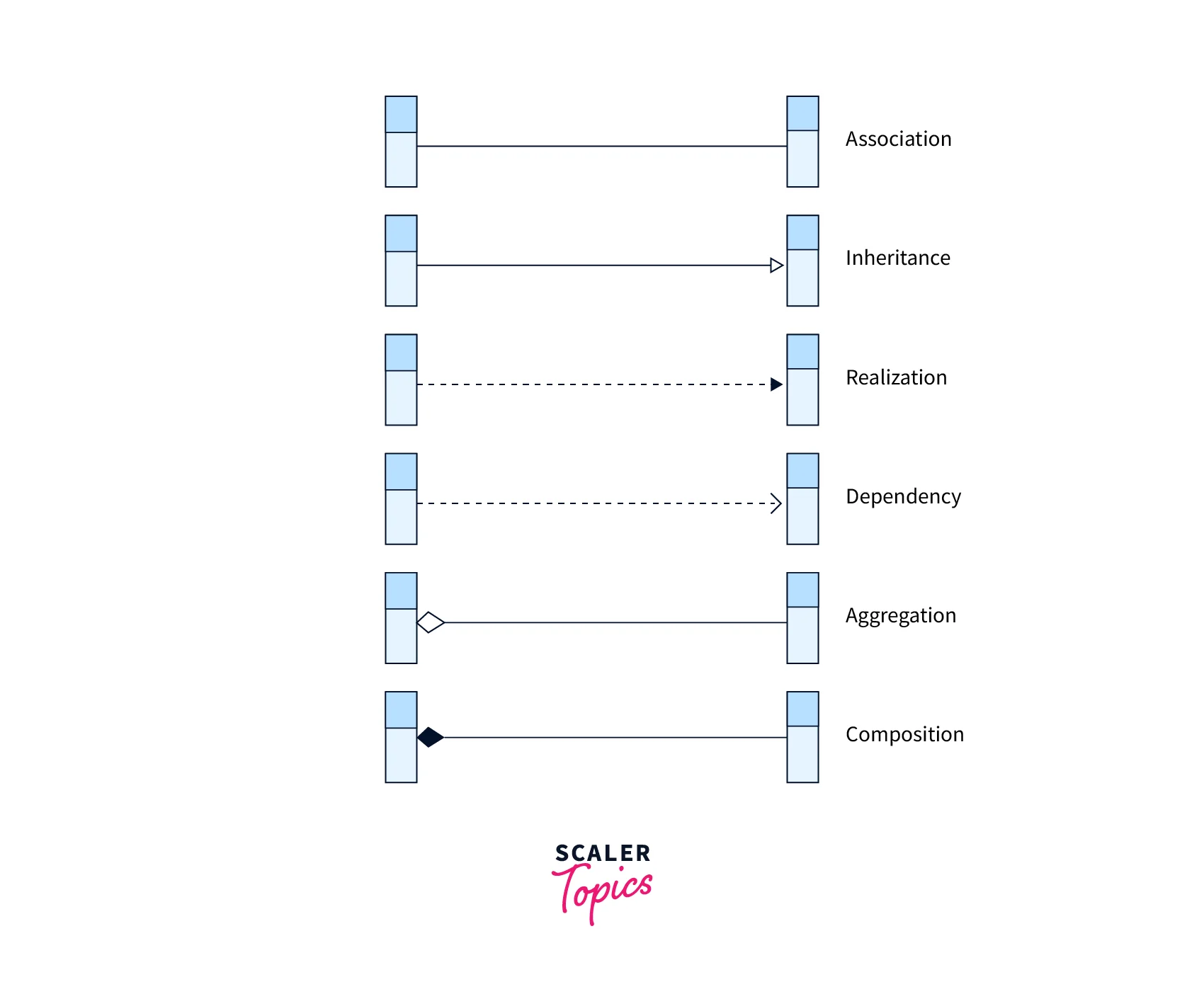
- Associations: Associations in a UML Class Diagram are relationships between classes. A solid line between classes is used to represent them. Associations are often labeled with a verb or verb phrase that matches the problem area in the real world.
- Generalization or inheritance: A taxonomic link between a broader and a more particular classifier is referred to as an inheritance or generalization. Each classifier instance is also an indirect instance of the general classifier. As a result, the particular classifier inherits the characteristics of the more general classifier. It symbolizes an "is-a" relationship.
- Aggregation: The construction of a specific class as a result of one class being aggregated or formed as a collection is referred to as aggregation. The class "library," for example, consists of one or more books, among other items. The included classes in aggregate are not heavily dependent on the container's lifespan. To depict aggregation in a diagram, draw a line from the parent class to the child class with a diamond shape near the parent class.
- Composition: The composition relationship and the aggregation connection are extremely similar. The main distinction is that it emphasizes the contained class's reliance on the life cycle of the container class. That is, when the container class is destroyed, the enclosed class is eliminated. A bag's side pocket, for example, will no longer exist after the bag is destroyed.
- Realisation: The implementation of functionality defined in one class by another class is referred to as realization. In UML, a broken line with an unfilled solid arrowhead is sketched from the class that defines the functionality to the class that implements the function to demonstrate the relationship.
- Dependency: In the code of a method, an object of one class may use an object of another class. If the object is not kept in any field, the relationship is portrayed as a dependency.
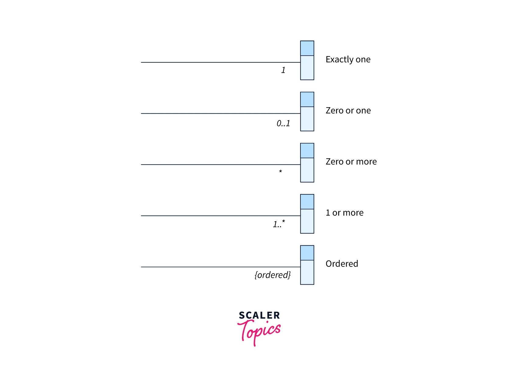
- Cardinality: Cardinality is expressed as one-to-one, one-to-many, or many-to-many relationships.
How to Draw a Class Diagram
Step 1: Determine the class names. The first step is to determine the system's primary objects.
Step 2: Separate relationships The next step is to figure out how each of the classes or objects is connected to the others. Look for commonalities and abstractions between them to aid in grouping them while building the class diagram.
Step 3: Build the Structure Add the class names first, then connect them with the required connectors. Attributes and functions/methods/operations can be added afterward.
Example
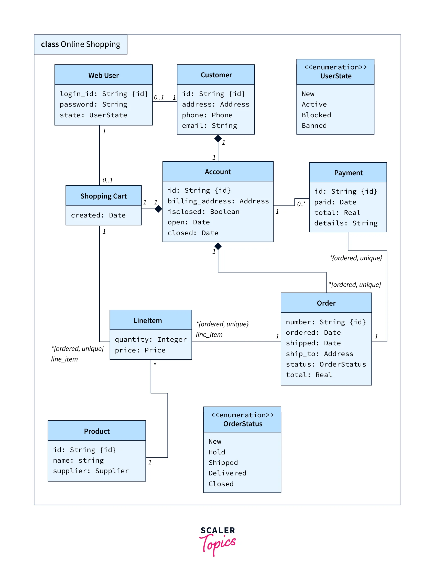
The following is a class diagram for an online shopping app. Notice the Class' attributes, methods, and their visibility. Also, notice the relationships among different classes and their cardinality as well.
Conclusion
- Class Diagrams are one of the most significant diagrams in coding since they serve as the foundation for component and deployment diagrams and clarify system roles.
- In addition, they are utilized for application analysis and design, as well as forward and reverse engineering.
- They are typically used to investigate domain concepts, comprehend software requirements, and define intricate architectures.
- There are various tools available for drawing UML diagrams online and explaining various aspects of software development visually.