Data Link Layer in OSI Model
Overview
- Data Link Layer is the second layer of the seven-layer OSI model that is responsible for simply ensuring and confirming that the bits and bytes received are similar to the bits and bytes being transmitted. It is essentially a set of standards that are used for implementing the data link layer of the Open System Interconnections (OSI) Model just above the physical layer.
- The problem with the data link layer (and much of the upper levels) is how to prevent a fast transmitter from drowning a slow receiver in data. A traffic control method is frequently required to inform the transmitter of how much buffer space the receiver currently has. Flow regulation and error management are frequently used techniques for controlling this problem.
- In the data link layer, broadcast networks face an additional challenge: How to control access to the shared channel. The Medium Access Control (MAC) sublayer of the data link layer is responsible for dealing with this issue.
What is the Data Link Layer Protocol?
- The data link layer is the second layer of the seven-layer OSI model of computer networking. This is the protocol layer that transports data between network nodes in a wide area network (WAN) or nodes in the same local area network (LAN).
- The data link layer is one of the most complex layers, with numerous liabilities and functionalities. The data link layer conceals the underlying hardware features and represents itself as the communication medium to the upper layer.
- The data link layer connects two hosts that are in some ways directly connected. This direct link could be either point-to-point or broadcast.
- The data link layer is accountable for transforming data streams to signals bit by bit and transmitting them across the underlying hardware. At the receiving end, the data link layer collects data from hardware in the form of electrical signals, assembles it into a recognizable frame format, and passes it to the top layer.
- The data link layer is also responsible for delivering frames between devices on the same LAN. The primary function of the Data Link Layer is to transmit the datagram via an individual link. It performs this task by breaking up the input data into data frames(usually a few hundred or a few thousand bytes) and broadcasting the frames sequentially. If the service is reliable, the receiver acknowledges receipt of each frame by sending back an acknowledgment frame.
- Ethernet for local area networks (multi-node), Point-to-Point Protocol (PPP), HDLC, and ADCCP for point-to-point (dual-node) connections are examples of data link protocols.
Some Common Data Link Protocols are:
- Synchronous Data Link Protocol (SDLC): SDLC is a protocol for transmitting synchronous, code-transparent, serial-by-bit data across a communications line.
- High-Level Data Link Protocol (HDLC): HDLC is a series of data link layer communication protocols for sending data between network points or nodes.
- Serial Line Interface Protocol (SLIP): SLIP is an Internet protocol that allows users to connect to the Internet via a computer modem.
- Point to Point Protocol (PPP): PPP is used to connect two computer systems. Computers use PPP to communicate through a telephone network or the Internet.
- Link Control Protocol (LCP): LCP is a component of (PPP) that is in charge of establishing, configuring, testing, managing, and terminating transmission lines. It also imparts negotiation for option setup and features used by the two endpoints of the links.
- Link Access Procedure (LAP): LAP protocols are Data Link Layer protocols that are used to frame and transfer data via point-to-point lines.
- Network Control Protocol (NCP): NCP is a mechanism for establishing and configuring various Network Layer protocols for Point-to-Point Protocol (PPP) connections.
Functions of Data Link Layer
Scaler Placement Report and Statistics
Scaler learners achieved 2.5x salary growth with average post-Scaler CTC reaching ₹23L.
1) Framing and Link Access

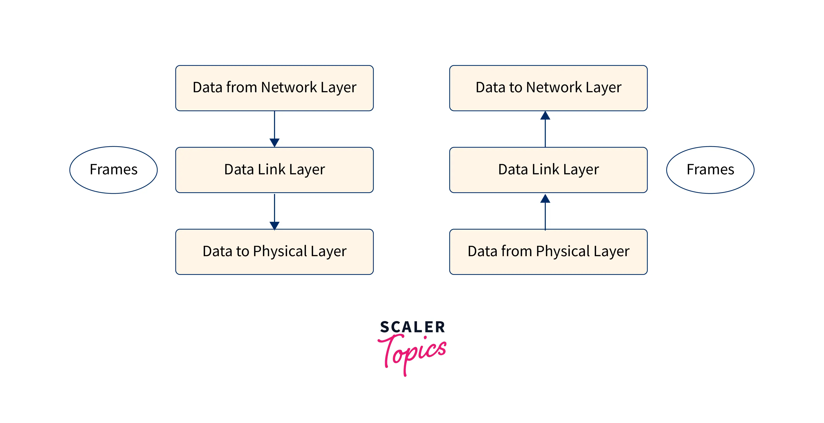
- The data-link layer takes packets from the network layer and encapsulates these packets into frames. A frame is a collection of a data field in which a network layer datagram is put along with a number of data fields. It defines the frame's structure and the channel access protocol that will be used to transmit the frame over the link. Then it sends each frame bit by bit on the hardware.
- Frames are the streams of bits received from the network layer that are converted into manageable data units. The Data Link Layer divides the bit stream. At the receiver's end, the data link layer collects signals from hardware and assembles them into frames.
2) Reliable Delivery
The Data Link Layer provides a guaranteed delivery service, i.e., it transmits network layer datagrams without error. Transmissions and acknowledgments are used to provide a reliable delivery service. A data link layer typically offers a reliable delivery service over links since they have high error rates and can be repaired locally, rather than causing the data to be retransmitted.
Transform Your Career
Choose from our industry-leading programs designed for career success
Modern Software and AI Engineering Program
Master full-stack development with AI integration

Modern Data Science and ML with specialisation in AI
Advanced data science techniques with AI specialization
Advanced AIML with Specialisation in Agentic AI
Deep dive into AIML with focus on Agentic systems
DevOps, Cloud & AI Platform Engineering
Build and manage AI-powered cloud infrastructure
AI Engineering Advanced Certification by IIT-Roorkee
Premier AI engineering certification from IIT-Roorkee
3) Flow Control
- Stations on the same link may have varying speeds or capacities. The data-link layer ensures flow control, allowing two machines to transmit data simultaneously.
- A receiving node can receive frames more quickly than it can process them. Without flow control, the receiver's buffer can overflow, which will result in frame loss. To address this issue, the data connection layer employs flow control to keep the sending node on one side of the network from overwhelming the receiving node.
4) Error Control
Signals may experience problems during the transition, and the bits may get inverted. These errors are recognized and attempted to be recovered by the data link layer in order to retrieve actual data bits.
- Error detection: Signal attenuation and noise can both generate errors. The Data Link Layer protocol provides a mechanism for detecting one or more errors. This is accomplished by adding error detection bits at the end of each frame, which allows the receiving node to do an error check.
- Error correction: This is similar to error detection, in which the receiving node not only detects errors but also determines where the faults occurred in the frame.
5) Physical Addressing
- The data-link layer provides a mechanism for layer-2 hardware addressing. If the frames are to be sent to multiple systems on the network, the Data Link layer adds a header to the frame to identify the physical address of the sender or receiver.
- Hardware addresses are expected to be unique on the link. It is encoded into devices throughout the manufacturing process.
6) Multi-Access
When a host on the shared link tries to send data, there is a significant chance of a collision. The data-link layer provides mechanisms such as CSMA/CD that enable different systems to access shared media.
Error Detection and Correction in Data Link Layer
The data-link layer employs error control techniques to ensure that frames (bit streams of data) are accurately delivered from the source to the destination.
Errors
Bits might get damaged while transported over a computer network due to interference and network difficulties. Errors occur when corrupted bits cause spurious data to be received by the destination.
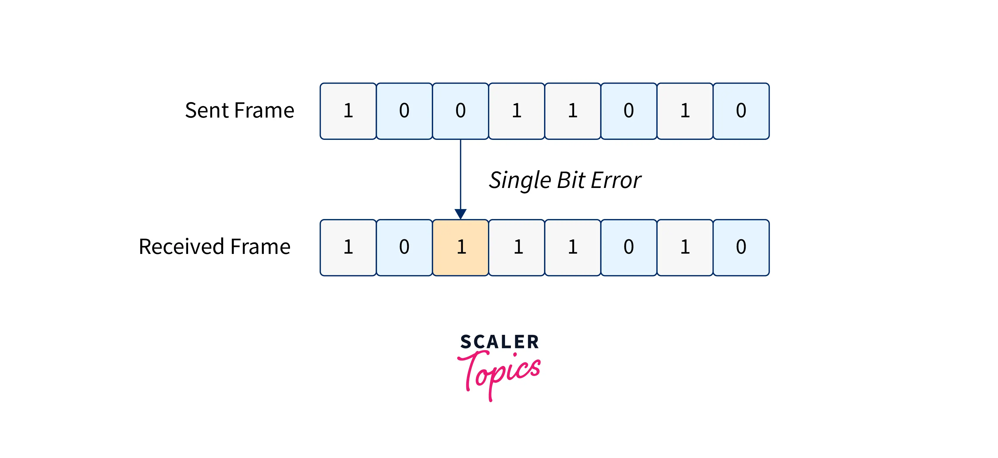
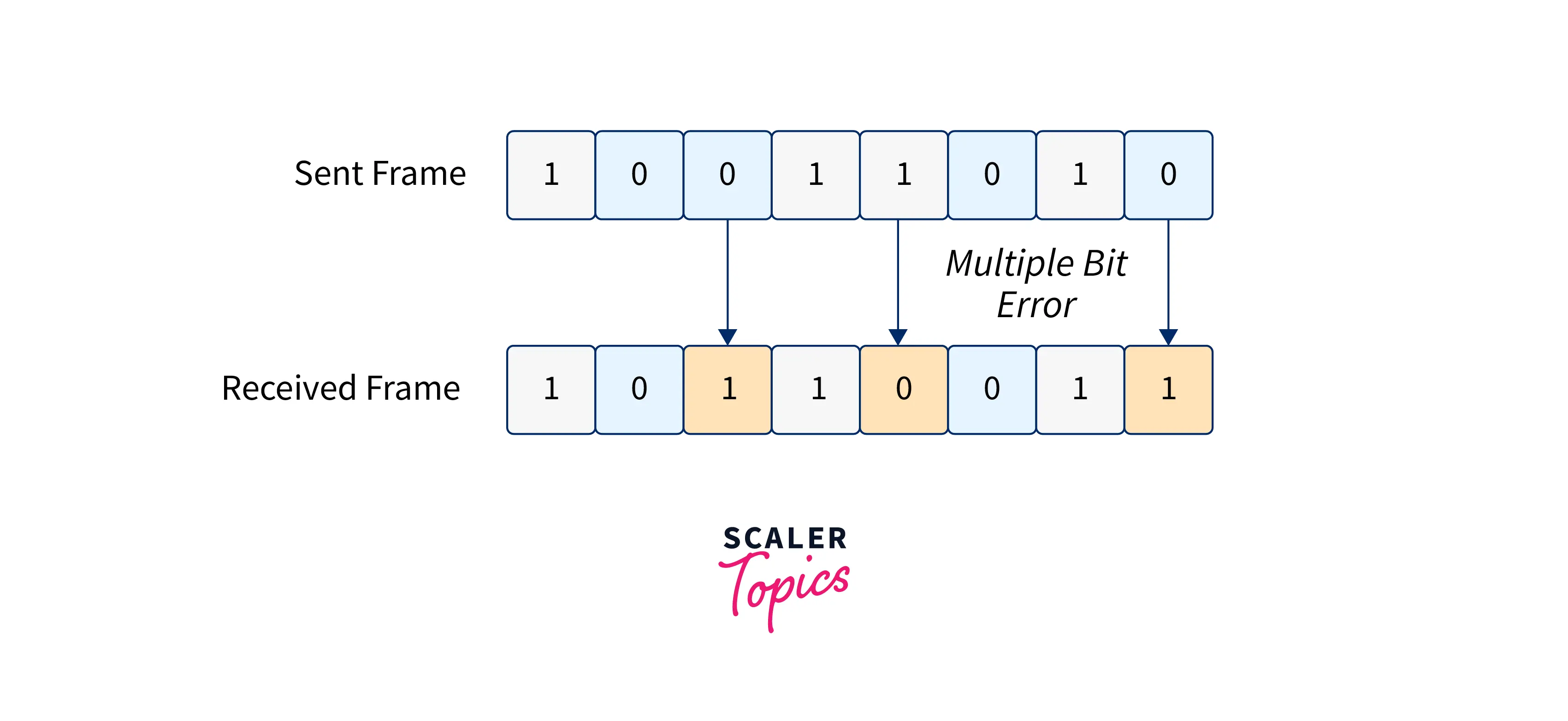
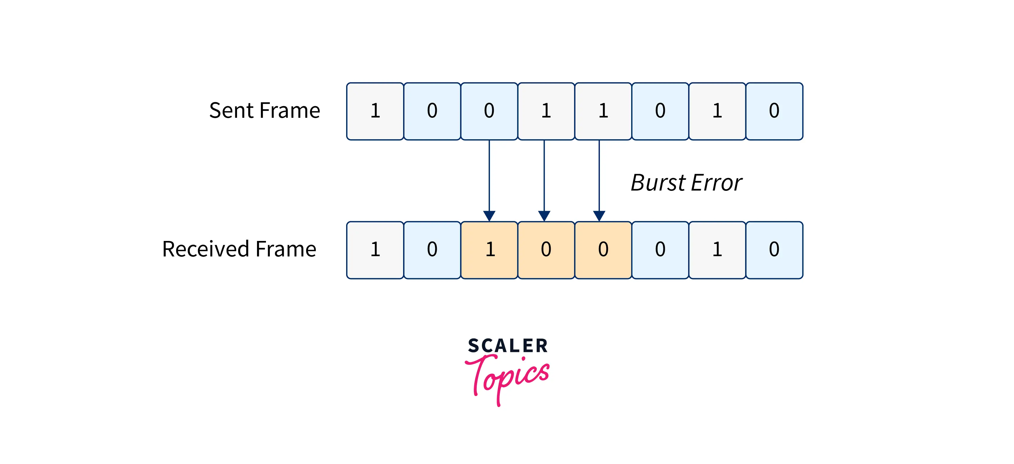
Types of errors: Errors are classified into three types: single-bit errors, multiple-bit errors, and burst errors.
- Single Bit Error: Only one bit in the received frame has been corrupted, i.e., it has changed from 0 to 1 or from 1 to 0.
- Multiple-bit Error: More than one bit in the received frame is corrupted.
- Burt Error: More than one consecutive bit in the received frame is corrupted.
Error Control
There are two methods for controlling errors:
- Error detection- Error detection involves determining whether or not an error has occurred. The type of error and the number of error bits do not matter.
- Error correction- Error correction involves determining the exact number of corrupted bits and the location of the corrupted bits.
The sender must send some additional bits together with the data bits for error detection and correction. Based on the additional redundant bits, the receiver performs the necessary checks. If the data is error-free, it eliminates the unnecessary bits before delivering the message to the upper layers.
Turn Learning into Career Growth
Error Detection Techniques
Three methods are used to detect an error in frames: Parity check, Checksum, and Cyclic Redundancy Check (CRC).
1. Parity Check The parity check is performed by adding an extra bit to the data known as the parity bit, which results in a number of 1s that are either even in the case of even parity or odd in the case of odd parity. The parity check is only useful for detecting single-bit errors.
The sender counts the amount of 1s in the frame and adds the parity bit in the following manner:
- Even parity: If the number of 1s is even, the parity bit value will be 0. The parity bit value will be 1 if the number of 1s is odd.
- Odd parity: If the number of 1s is odd, the parity bit value will be 0. The parity bit value will be 1 if the number of 1s is even.
When a frame is received, the receiver counts the number of 1s in it. In the case of an even parity check, the frame is accepted if the number of 1s is even; otherwise, it is refused. A similar approach is used for odd numbers.

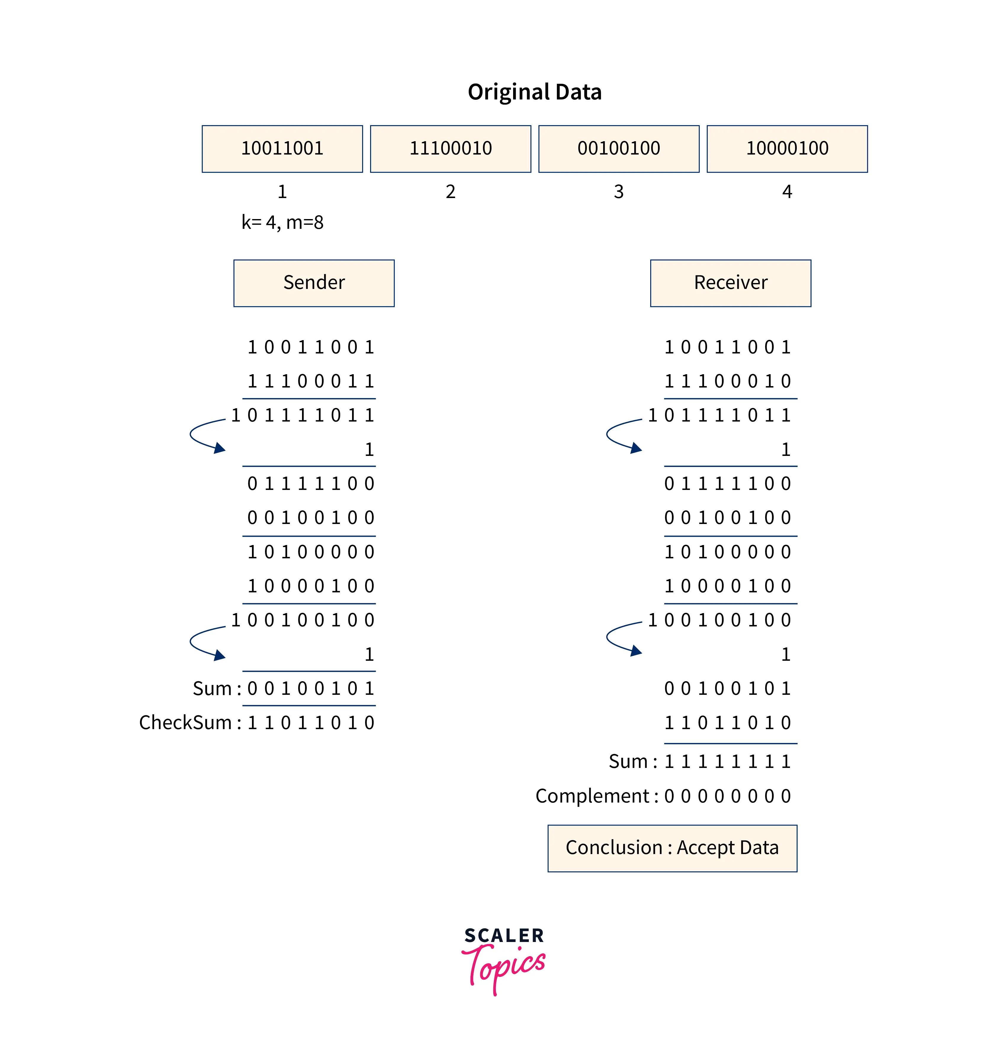
2. Checksum
- In this error detection scheme, the data is broken down into fixed-size frames or segments.
- To calculate the sum, the sender adds the segments using 1's complement arithmetic. It then adds the sum to get the checksum, which it sends along with the data frames.
- The receiver adds the incoming segments and the checksum to acquire the sum and then complements it using 1's complement arithmetic.
- The received frames are accepted if the result is zero; else, they are discarded.
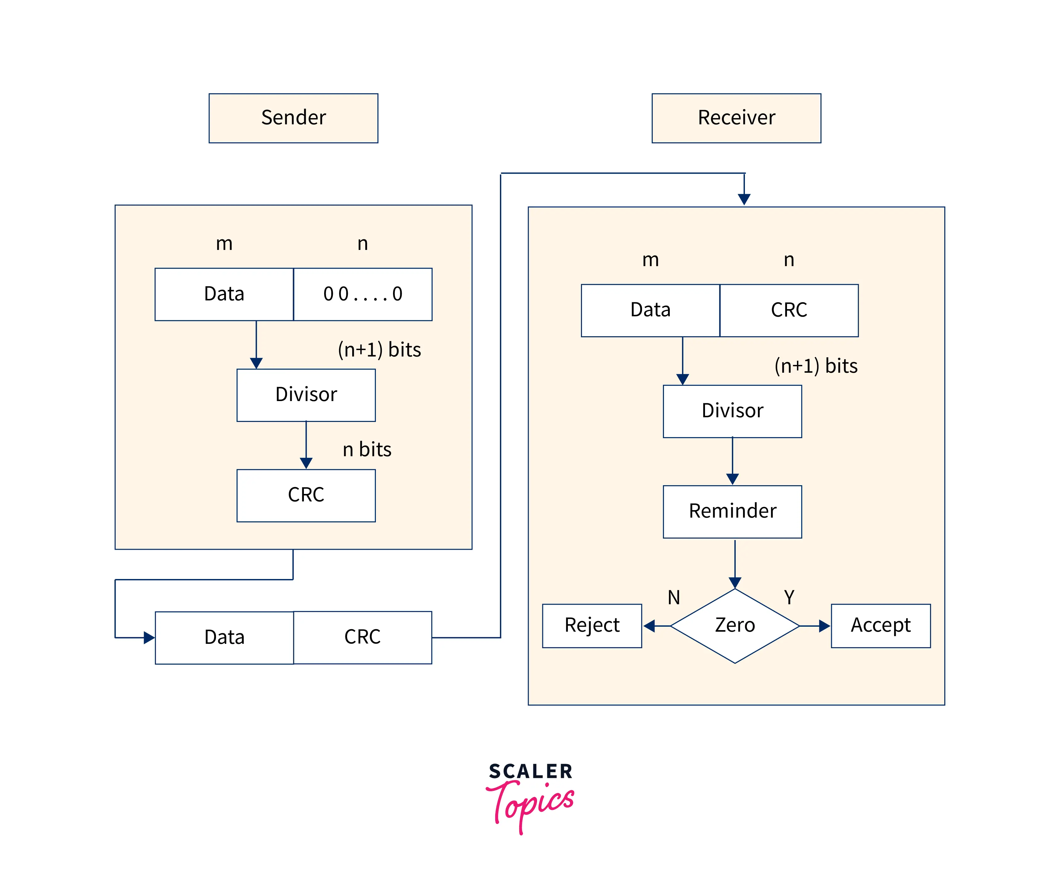
3. Cyclic Redundancy Check (CRC)
- CRC (cyclic redundancy check) is a technique for detecting errors in digital data. The CRC is a type of checksum that generates a fixed-length data set depending on the construction of a file or a bigger data set. CRC is a hash function that identifies accidental modifications to raw computer data and is widely used in storage devices such as hard disc drives and digital telecommunications networks.
- CRC is a binary division-based checksum that is also known as a polynomial code checksum. A specified number of check bits, commonly referred to as a checksum, are appended to the message that must be conveyed during the cyclic redundancy check. The receivers receive the data and look for mistakes in the check bits.
Error Correction Techniques
Error correction techniques determine the exact number of corrupted bits and their positions. There are two main approaches.
- Backward Error Correction (Retransmission) − It is a straightforward method. If the receiver identifies an error in the incoming frame, it requests the sender to retransmit the frame. However, it can be used efficiently only when retransmission is not expensive, such as in fiber optics, and the time required for retransmission is short in comparison to the application's requirements.
- Forward Error Correction − If the receiver identifies an error in the incoming frame, it performs an error-correcting code that generates the actual frame. This reduces the amount of bandwidth required for retransmission. In real-time systems, it is essential. However, if too many faults are found in the frames, they must be retransmitted.
The four major error-correcting codes are as follows:
- Hamming Codes
- Binary Convolution Code
- Reed – Solomon Code
- Low-Density Parity-Check Code
Design Issues with Data Link Layer
Network Layer Service Agreement
The primary goal of this service is to provide services to the network layer. The main aim of the data link layer is to transmit data from the network layer on the source machine to the layer on the destination machine. The Data Link Control Protocol is used to communicate between the two data levels.
The Data Link layer provides the following essential services to the Network layer:
- Unacknowledged connectionless services: This is a connectionless service in which the sender transmits a message, and the receiver receives it without acknowledgment.
- Acknowledged connectionless service: The sender transmits the message to the receiver, and the receiver acknowledges receipt of the message to the sender using connectionless services.
- Acknowledged-oriented service: In this service, both the sender and the receiver use connection-oriented services, and communication between the two nodes is based on acknowledged base communication.
Framing
The data is sent to the destination machine in the form of frames from the source machine. The starting and ending points of the frame should be highlighted so that the destination machine can clearly recognize the frame.
The data link layer divides the bitstream into layers and computes the checksum for each. The checksum is enumerated at the destination layer. Framing is the process of breaking up a bitstream by inserting spaces and time gaps.
Counting on time and marking the beginning and end of each frame is challenging and dangerous. Simple techniques used in framing are:
- Character Count
- Starting and ending character with character filling
- Starting and ending flags with little fillings.
Flow Control
- Flow control is used to stop data flow at the receiver. The frames will be transferred to the receiver extremely fast by the transmitter. However, the sender operates on a lightly loaded system, and the receiver runs on a substantially loaded machine; therefore, the receiver will not be able to take them as rapidly as the sender sends them.
- It makes no difference if the transmission is flawless at some moment. The receiver will be unable to control the arriving frames.
- There is a mechanism that requests the transmitter to block the wrong signals in order to stop the broadcast.
Scaler Placement Report and Statistics
Scaler learners achieved 2.5x salary growth with average post-Scaler CTC reaching ₹23L.
Error Control
- It is done to ensure that no frames are copied and that the frames arrive safely at their destination. Moreover, positive and negative acceptance of incoming frames is sent.
- As a result, if the sender receives positive acceptance, the frame appears safely, whereas a negative appearance indicates something is wrong with the frame and will be retransferred.
- The timer is set at both the receiver and sender ends. Additionally, the outgoing transmission is assigned a sequence number. So, the receiver will quickly recognize that it is a retransmitted frame. It is one of the main tasks of the data link layer.
Physical Address of Frames
The data link layer appends a header to the frame that describes the physical address of the sender or receiver.
Enroll in our Free Computer Networking course with certification designed by industry experts. Sign up today & pave the way for a thriving career!
Conclusion
- The data link layer is in charge of collecting sets of bits for transmission as packets and ensuring that the packets get from one end to the other.
- Furthermore, physical layer transmission sometimes generates errors while the data link layer handles error detection (and sometimes correction).
- To ensure reliable transmission, the data link layer takes the data bits and "frames" and produces data packets.
- This layer adds the source, destination addresses, and information to detect and control transmission errors to the data stream.
- There are two sublayers in the data link layer. The logical link control (LLC) sublayer maintains the communication link between two network devices. The other sublayer is the media access control (MAC), which regulates data transmission between two devices.
- The issue with the data link layer (and much of the upper levels) is preventing a fast transmitter from drowning a slow receiver in data. A traffic control approach is necessary to advise the broadcaster of the receiver's current buffer space. Flow regulation and error control are frequently combined to address this issue.