Physical Layer in OSI Model
Overview
OSI (Open System Interconnection) model is a conceptual model that is used to describe seven layers that computer systems use to communicate over a network. This model has been described in the form of 7 layers namely, Physical layer, Network layer, Data Link layer, transport layer, session layer, presentation layer and the application layer. All these 7 layers work together to transmit the data from one person to another across the globe.
Physical layer in the OSI model is the first and the lowest layer of the OSI reference model. It is responsible for controlling the way unstructured, raw, bit-stream data is sent and received over a physical medium.
What is the Physical Layer in OSI Model?
Physical layer in the OSI model is the lowest layer of the OSI reference model. It is responsible for sending raw bits from one computer to another computer over a network. It does not deal with the data of these bits and is majorly concerned with the setup of physical connection to the network. It plays the role of interacting with actual hardware and signaling mechanisms.
It's the only layer of the OSI network model that deals with physical connectivity and is responsible for establishing, maintaining, and deactivating the physical connection of two different computing devices in a network. This layer defines the hardware equipment, topologies, cabling, modes of transmission, wiring, frequencies, pulses used to represent binary signals, etc.
 As we can see from the diagram above, the physical layer is the first and the lowest layer of the OSI model.
Functions of OSI Model Physical Layer
Following are some important and basic functions that are performed by the physical layer in the OSI model:
-
Topologies:
It defines the way how different computing devices in a network must be arranged with each other. Different types of topologies include Mesh, Star, Ring, and Bus. -
Configuration:
It refers to the way two or more communication devices are attached to a link. A Link is the physical communication pathway that transfers data from one device to another. For communication to occur, two devices must be connected in the same way to the same link at the same time.
There are two types of configurations : Point to Point Configuration and Multipoint Configuration. -
Transmission Modes:
It defines the direction of transmission between two devices. Different modes of transmission are Simplex, Half Duplex, and Full Duplex modes. -
Hardware Layer:
This layer comes under the category of Hardware Layer because it deals with the setting up of a physical connection to the network. -
Bits synchronization:
It deals with the Synchronization of bits. This means that the sender and the receiver are synchronized at bit level with the help of a clock. This clock controls both sender and receiver thus providing synchronization at the bit level. -
Bits rate control:
Physical Layer maintains the flow of data rate, i.e the number of bits sent per second from the sender to a receiver. -
Baseband and Broadband transmissions:
It also deals with baseband and broadband transmission connections. The baseband transmits the digital signal using a physical medium like wires and the broadband transmits the analog signals using optical fibers and twisted cables as a medium of transmission.
Scaler Placement Report and Statistics
Scaler learners achieved 2.5x salary growth with average post-Scaler CTC reaching ₹23L.
Physical Topologies
Physical Topologies show us the arrangement with which computer systems or devices are connected.
There are four major types of physical topologies defined :
Transform Your Career
Choose from our industry-leading programs designed for career success
Modern Software and AI Engineering Program
Master full-stack development with AI integration

Modern Data Science and ML with specialisation in AI
Advanced data science techniques with AI specialization
Advanced AIML with Specialisation in Agentic AI
Deep dive into AIML with focus on Agentic systems
DevOps, Cloud & AI Platform Engineering
Build and manage AI-powered cloud infrastructure
AI Engineering Advanced Certification by IIT-Roorkee
Premier AI engineering certification from IIT-Roorkee
1. Bus Topology
It is one of the simple forms of networking topology. Here multiple devices are connected through a single cable or a communication line that is known as the backbone cable. All the devices are connected via this single cable.
When any particular node or a device wants to send a message over the network to another device, then it puts a message over the network and all the stations available in the network will receive the message as they are connected with a single cable, whether they have been addressed or not. Bus topology is useful for peer-to-peer networks where each computing device can independently communicate with other devices over the network.
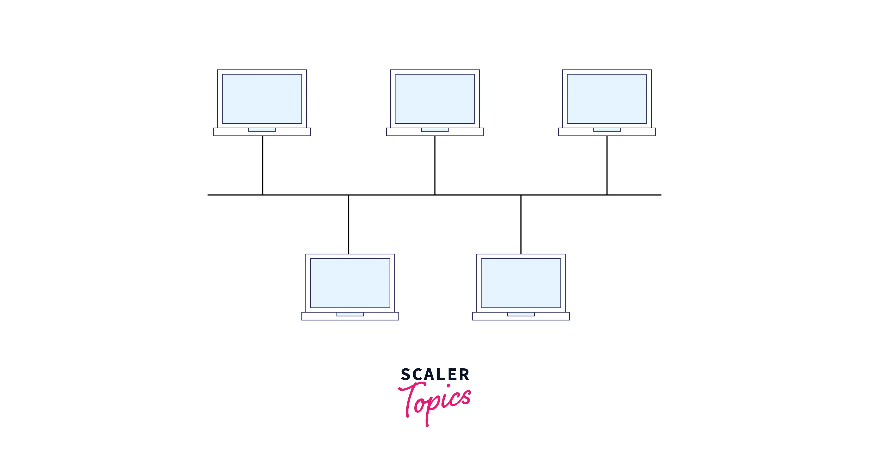
We can see from the diagram above that all the devices are connected to a single backbone cable.
Advantages of Bus topology:
- It is less costly as compared to other topologies as devices are connected to a single cable without any hub, and so the installation and connection charges are also less.
- A failure in one node will not have any effect on other nodes.
- It is simple and can be easily set up because more computer systems can be efficiently added to the same network without disturbing other connections.
Disadvantages of Bus topology:
- If two nodes send the messages simultaneously, then collision between the signals of both nodes will occur.
- Attenuation can be seen in a bus topology, It is a loss of signal that leads to communication issues. Repeaters are used to regenerate the signal.
- Data privacy is less in bus topology because of the single cable connection, each node can receive the message sent by some node, even when they have not been addressed.
2. Mesh Topology
In a mesh topology, every device has a point-to-point connection with every other device in the network. There are links in the mesh if there are N nodes as each device is connected to every other device in the network with the help of extensive cabling.
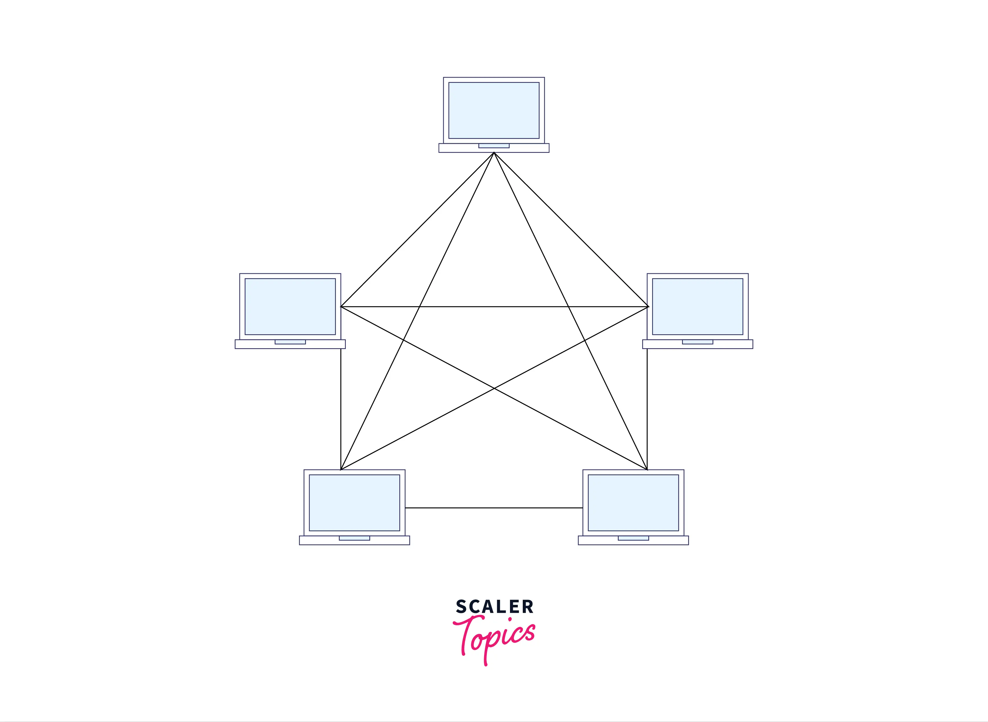
As we can see from the diagram above, all the devices are connected to all other devices.
Advantages of Mesh topology:
- Communication is very fast between the nodes of the network as it is an interconnection of all nodes connected with all other nodes in the network. So, each node has a dedicated link to another node.
- It is a reliable connection if any link breakdown occurs, it will not affect the communication between the connected computers.
Disadvantages of Mesh topology:
- It is complex and difficult to install as it has a more complex node arrangement.
- It is more costly than other topologies as its very difficult to establish the connections of the mesh topology.
- Redundant connections are high in a mesh topology, which reduces the efficiency of the network.
3. Star Topology
In star topology, each device has a dedicated point-to-point connection with a central controller or a hub. The central computer or a hub is known as a server, and the devices attached to the hub are known as clients.
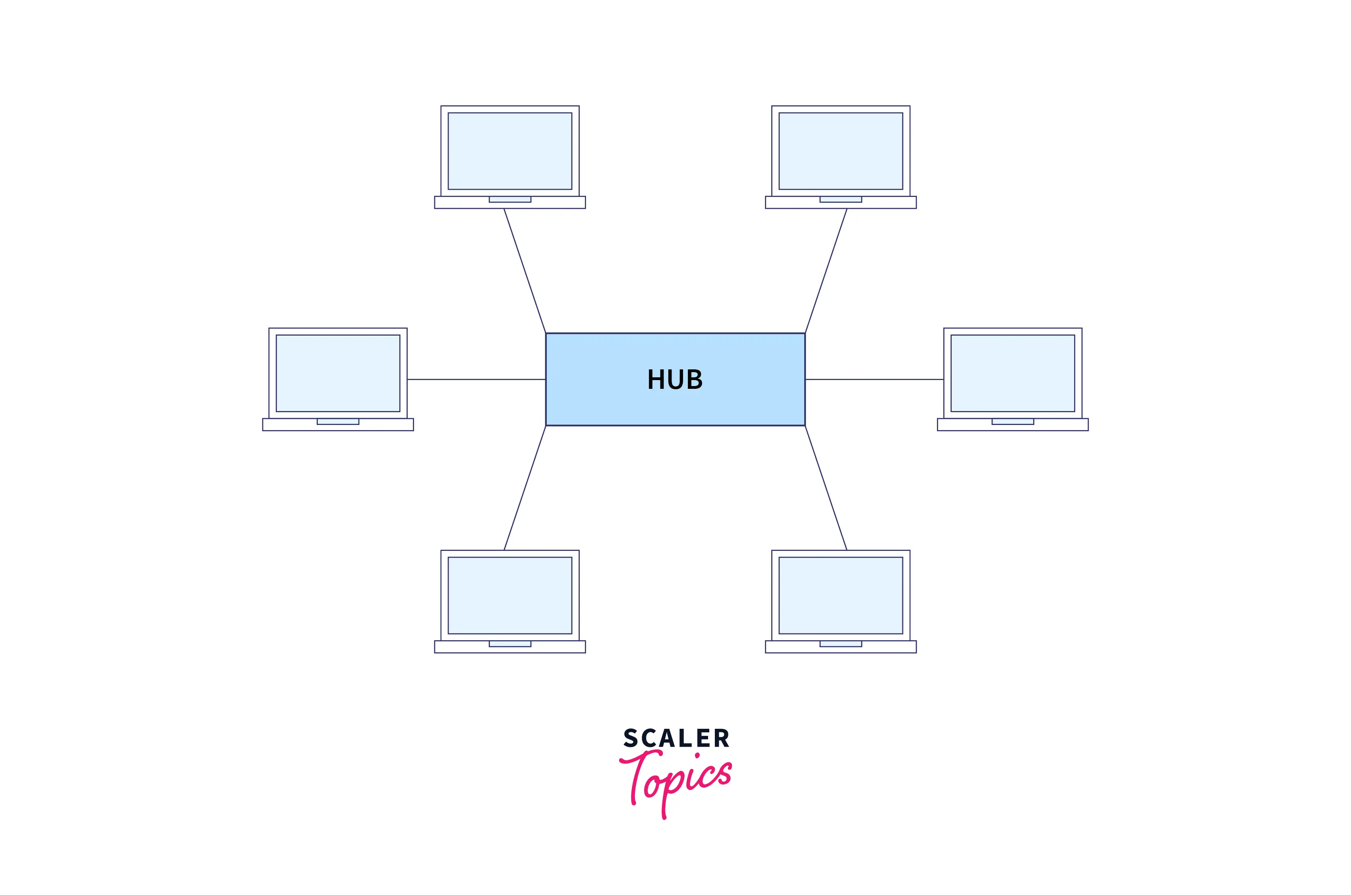
We can see from the diagram above that all the nodes are connected to the central hub or a server.
Advantages of Star topology:
- Star topology is easily expandable and we can easily add more devices to the open ports of the hub.
- Star topology networks are cost-effective as they use inexpensive cabling.
- Failure is less, because each device is connected to the central hub with its cable, so if failure in one cable occurs then it will not affect the entire network of devices.
Disadvantages of Star topology:
- It possesses a single point of failure in case of failure in the central hub.
- If the central hub goes down, then all the connected devices will not be able to communicate with each other.
- It is a complex arrangement of nodes.
4. Ring Topology
In ring topology, each device is connected to two other devices from both of its sides and this forms a circular ring of connected devices which gives it its name. Data gets transferred from one device to another in the form of a ring in a single direction known as the unidirectional flow of data.
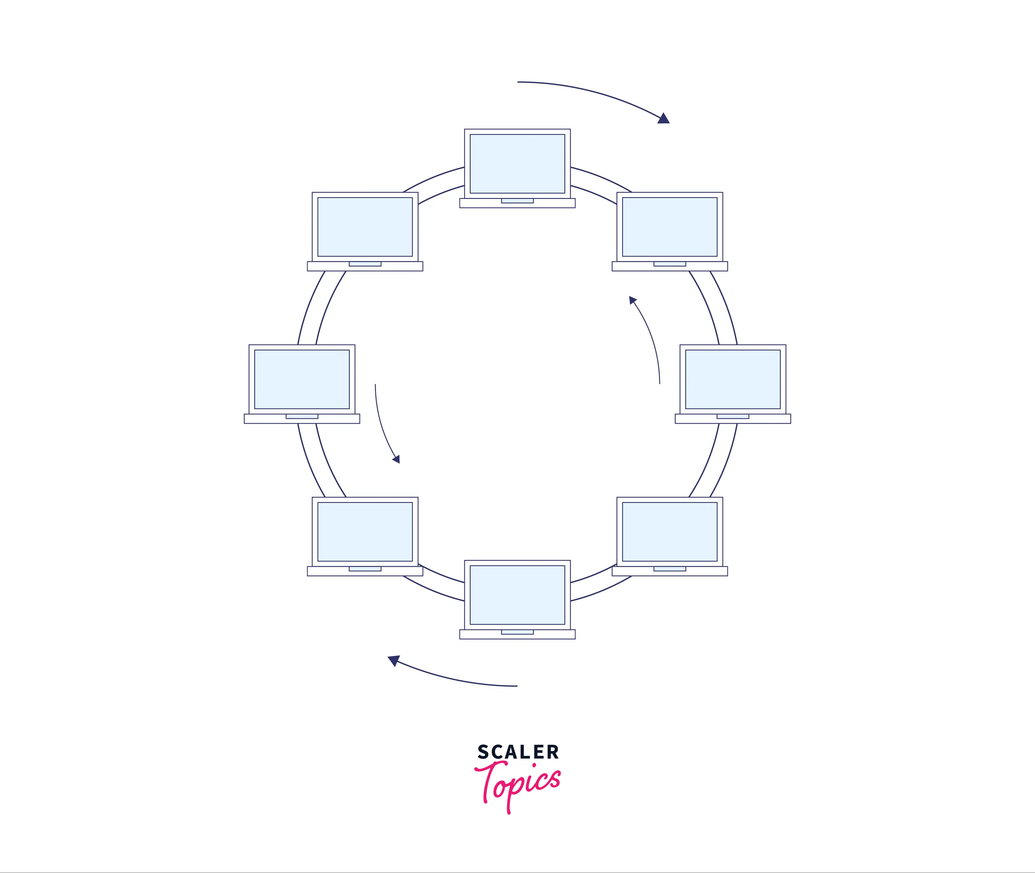
We can see from the diagram above that all the devices are connected in the form of a ring and data gets transferred in a unidirectional way.
Advantages of ring topology:
- If some fault occurs in any node/device of the network, then that faulty device can be easily removed from the network without disturbing other nodes in the network.
- It is a reliable network connection because the communication system is not dependent on a single host or the server computer.
Disadvantages of ring topology:
- Communication delay can be seen in the ring topology and adding new devices increases the communication delay. We can say that communication delay is directly proportional to the number of nodes.
- If any fault occurs in the cable itself, then it would disturb the network for all the nodes as all the nodes are connected via a single cable.
- Adding new devices to the network would slow down the network as the data passes through every device in the ring topology.
Turn Learning into Career Growth
Point-to-Point Configuration
As we know for connection, two or more devices should be linked to each other (connected), there are two possible types of connections that can occur, one is the point-to-point configuration and another one is the multi-point configuration.
The point-to-point configuration provides a dedicated linking or the cabling between two devices. The entire capacity of the link is reserved for the data transmission between those two devices. It is the simplest and the most efficient point of connection topology between the devices.
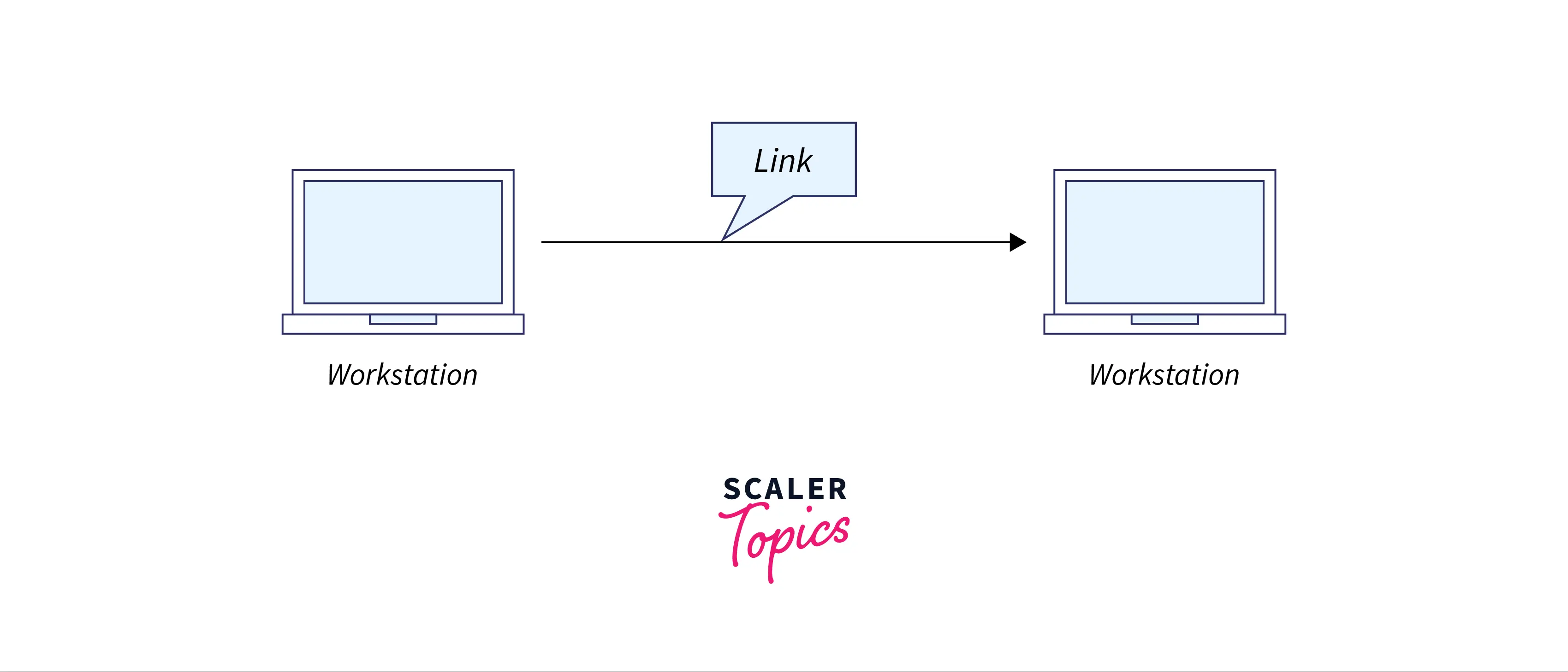 We can see from the diagram above that two workstations are connected via a single link.
Modes of Transmission Medium
Transmission mode or the medium in the physical layers states the way data is transmitted from one device to another, it also specifies the direction of transmission and hence is also known as the directional mode.
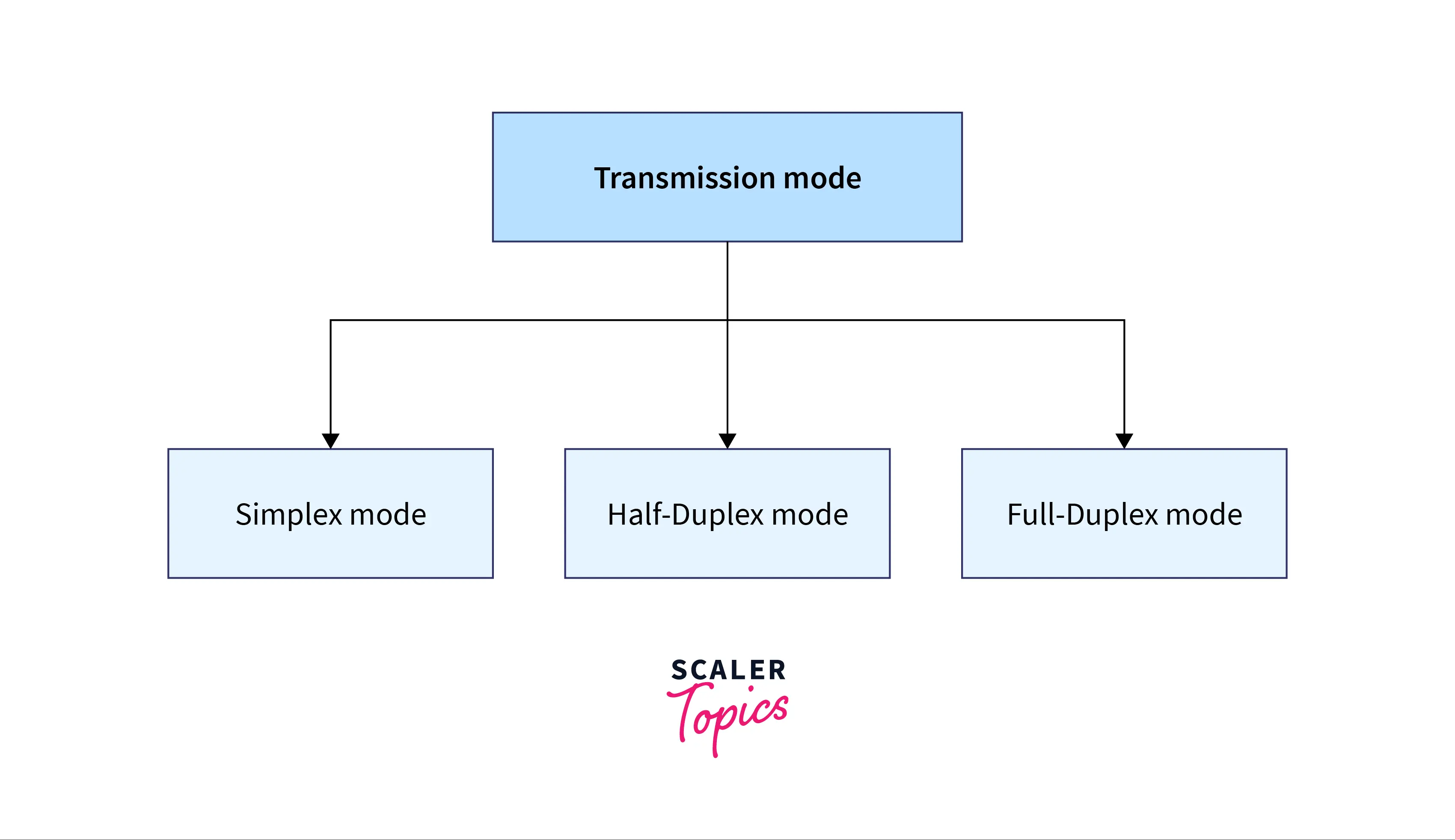
There are three types of transmission mediums:
1. Simplex Mode
In simplex mode, data is transferred from one device to another device in a single direction and hence is known as the unidirectional flow of data mode. Here, only one device can transmit the data, the other device can only receive the data. Senders can send data but can not receive it. Similarly, a receiver can only receive the data but can not send it.
Examples of simplex modes of communication include radios, TV, and broadcast. Keyboard and Monitor are also examples of the simplex mode as a keyboard can only accept the data from the user and a monitor can only display the data on the screen.
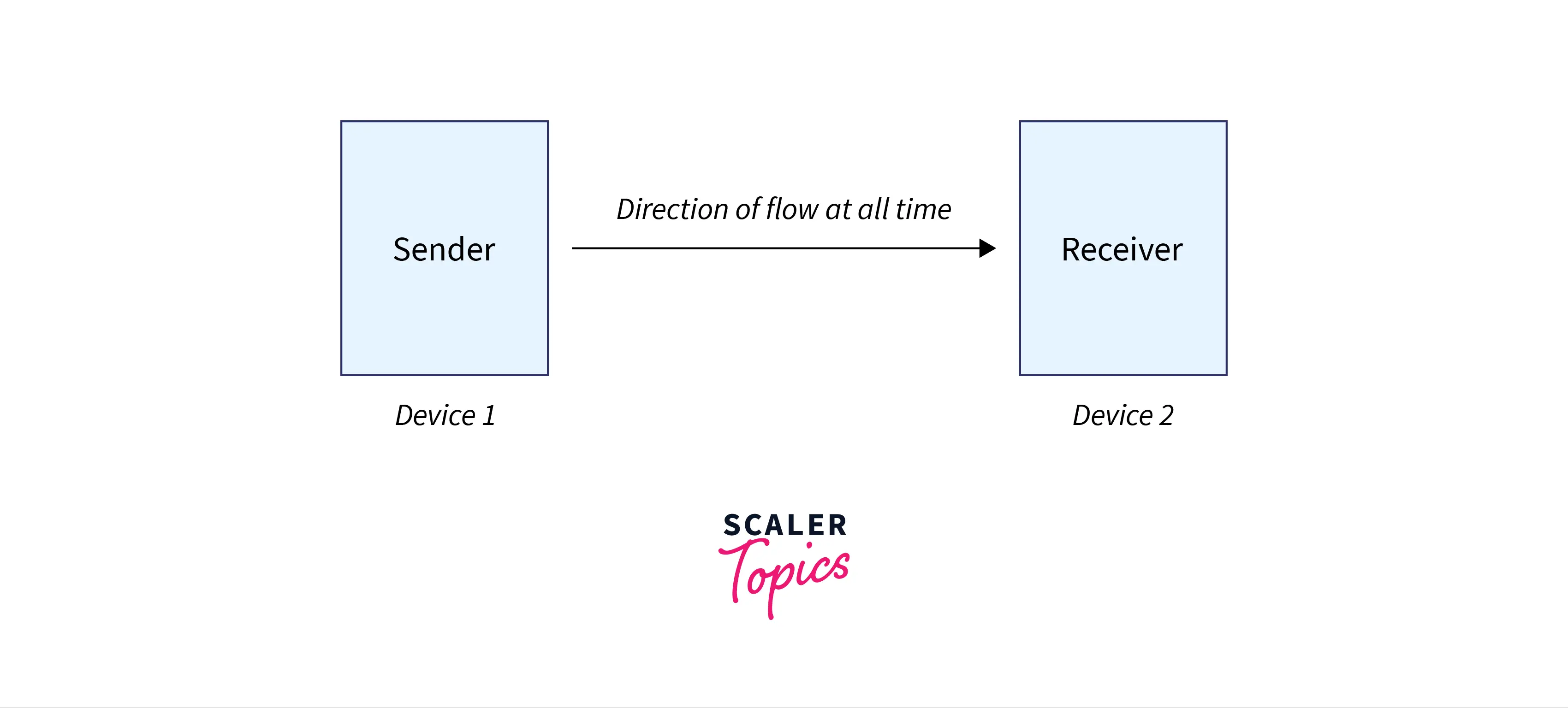
As we can see from the diagram above data always flows in one direction, i.e. from the sender to the receiver.
Advantages of Simplex mode:
- As the data flow is unidirectional and so it is a dedicated flow that helps in utilizing the full capacity of the communication channel during the transmission.
- Because of the dedicated flow, the full capacity of the communication channel can be utilized in the simplex mode of transmission.
Disadvantages of simplex mode:
- No inter-communication between devices is possible because of unidirectional flow.
- The simplex mode provides less performance as compared to other modes.
2. Half Duplex Mode
In half duplex mode, both the devices can send and receive the data but only one at a time and not simultaneously. Here, messages can flow in both directions, and hence it's a bi-directional flow of data, but we must understand the point that data cannot flow at the same time from both devices.
Walkie-Talkie, and Railway Track, are examples of half-duplex modes of transmission.
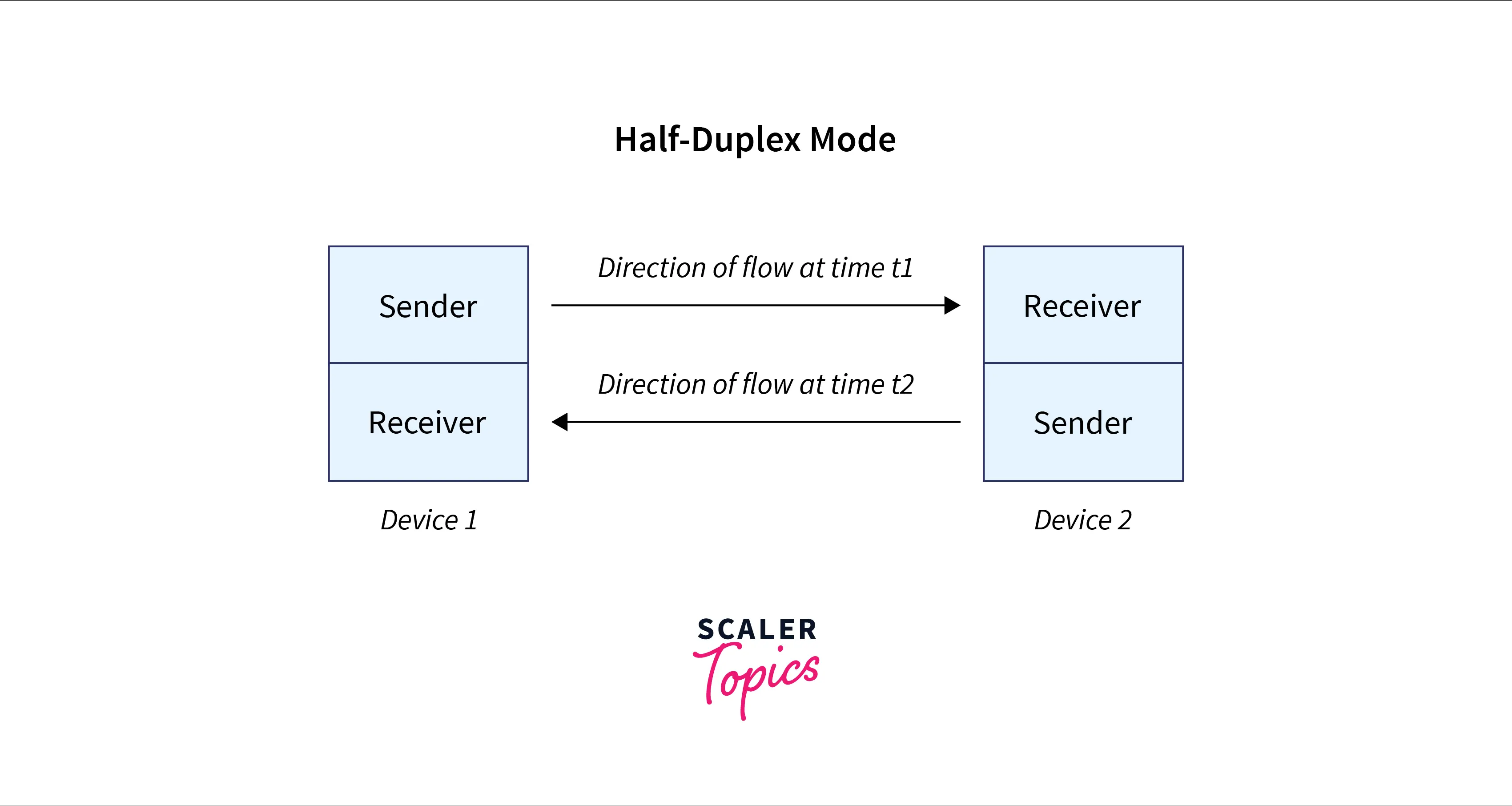
As we can see from the diagram above, the data is flowing in both directions but at two different times, i.e t1 and t2.
Advantages of Half duplex mode:
- Inter-communication between different devices is possible using half duplex mode as the devices can send and receive the data.
- The full capacity of the communication channel can be utilized in half-duplex mode because only one signal flows at a particular time.
Disadvantages of Half duplex mode:
- In the half-duplex mode of transmission, one device can send the data at a time, so another device needs to wait, and this causes the delay.
- The Half-Duplex involves lesser utilization of a single bandwidth at the time of transmission as at a point in time, only one device can send the data.
3. Full Duplex Mode
In full duplex mode, the communication is bidirectional and both the devices can send and receive the data at a time. Therefore it is the fastest mode of communication between devices. As the communication occurs simultaneously, two channels are there in the full duplex mode, one for sending the data from sender to receiver and another for sending the data from receiver to sender.
Telephone lines and mobile phones are examples of the full duplex mode of transmission as both persons can talk and share information simultaneously.
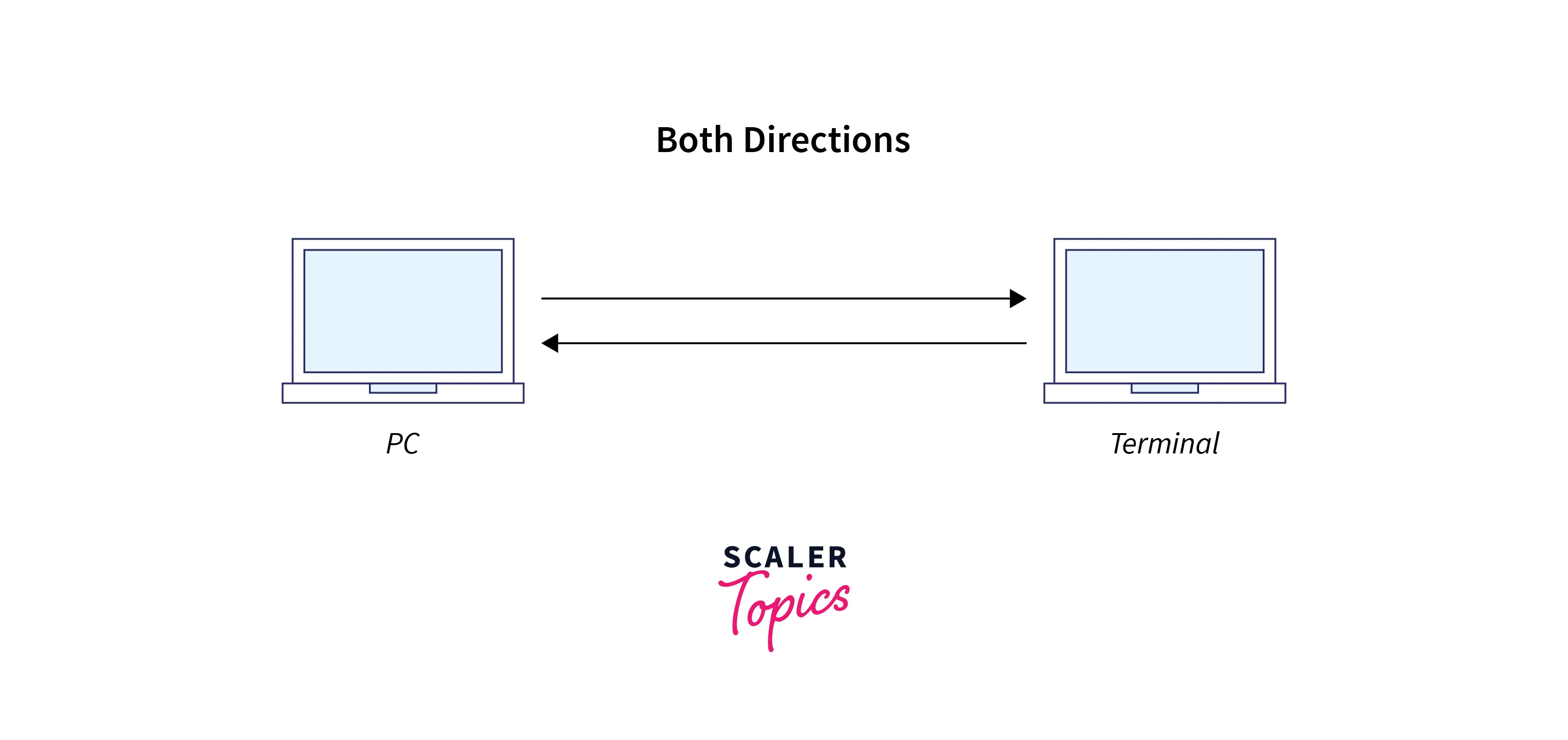
As we can see from the diagram above, the data is being transferred in both directions simultaneously.
Advantages of Full duplex mode:
- Both devices can send and receive the data at the same time, hence fast inter-communication is possible.
- The speed of full-duplex mode is higher than simplex and half-duplex mode.
Disadvantages of Full duplex mode:
- It is more complex than a simplex and half-duplex mode because the signal is sent in both directions at the same time.
- It is more expensive than other modes of transmission.
Design Issues with Physical Layer in OSI Model
- Major design issue with the Physical layer in the OSI model is the error handling, i.e if a sender sends a 1 bit, then at the receiver end it should be received a bit 1 only, and not a bit 0.
- Physical layer is concerned with sending raw bits of data over the communication channel.
- The design issues majorly deal with mechanical, electrical, and the physical transmission medium, which lies below the physical layer.
Scaler Placement Report and Statistics
Scaler learners achieved 2.5x salary growth with average post-Scaler CTC reaching ₹23L.
Conclusion
-
Physical layer in the OSI model is the lowest layer of the OSI reference model. It's responsible for sending raw bits between different devices.
-
The Physical layer in the OSI model deals with the hardware requirements of a network.
-
Physical layer topologies define how the different devices/nodes are arranged in a network, and different topologies include bus, star, ring, or mesh topology.
-
The bus topology all the devices in the network are connected by one central cable, in the star topology all the devices are physically connected to a central node such as a router, hub or switch, in mesh topology all the devices are connected to every other device, in ring topology, the circular ring of connected devices is formed.
-
Physical layer in the OSI model also defines how the data flows or transfers between the two connected devices. These are called the transmission modes, and we have three different transmission modes, i.e simplex, half duplex, and full duplex mode.
-
In simplex mode unidirectional flow of data is there, in half duplex mode data flows in bidirectional form but not at the same time from the sender and the receiver, in full duplex mode data flows in bidirectional form, both at the same time from the sender and the receiver.
-
Some design issues with the Physical layer in the OSI model include sending of raw bits of data and the error handling of the raw bits on both sides of the channels.