Error Detection and Correction in Computer Networks
Overview
Errors are introduced into the binary data transmitted from the sender to the receiver due to noise during transmission. The error can be a single-bit error, multi-bit error, or burst error. Error detection methods are used to check whether the receiver has received correct data or corrupted data. And error correction is used to correct the detected errors during the transmission of data from sender to receiver.
Errors in Communication
When the information received at the receiver end does not match the sent data. At the time of transmission, errors are introduced into the binary data sent from the sender to the receiver due to noise during transmission. This means that a bit having a 0 value can change to 1 and a bit having a 1 value can change to 0.
Scaler Placement Report and Statistics
Scaler learners achieved 2.5x salary growth with average post-Scaler CTC reaching ₹23L.
Types of Errors
Some errors that occur during communication are given below:
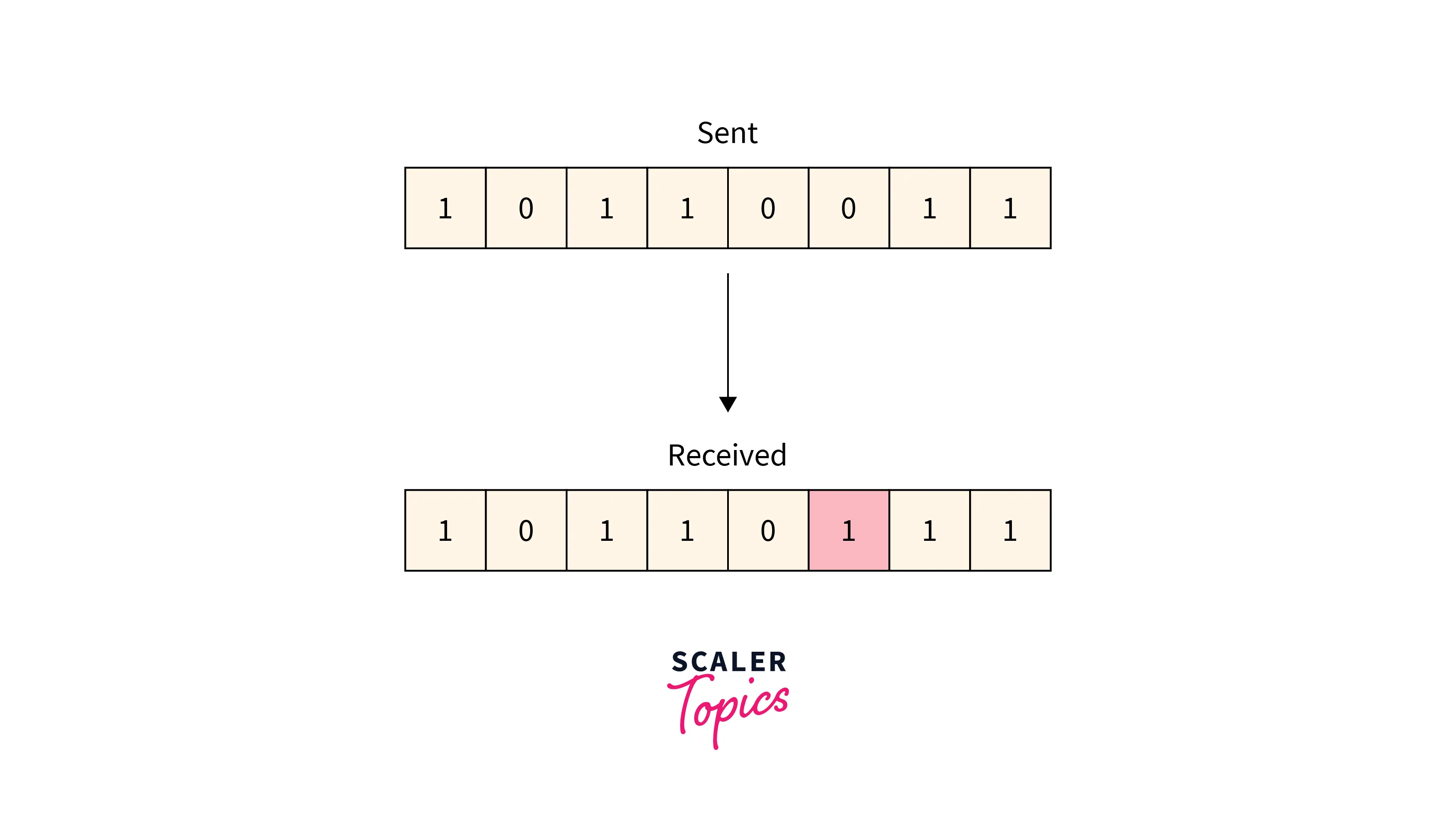
Single-bit Error
Typically, only one bit of the frame received is corrupt, and the corrupted bit can be located anywhere in the frame.
Refer to the below image for the single-bit error
Transform Your Career
Choose from our industry-leading programs designed for career success
Modern Software and AI Engineering Program
Master full-stack development with AI integration

Modern Data Science and ML with specialisation in AI
Advanced data science techniques with AI specialization
Advanced AIML with Specialisation in Agentic AI
Deep dive into AIML with focus on Agentic systems
DevOps, Cloud & AI Platform Engineering
Build and manage AI-powered cloud infrastructure
AI Engineering Advanced Certification by IIT-Roorkee
Premier AI engineering certification from IIT-Roorkee
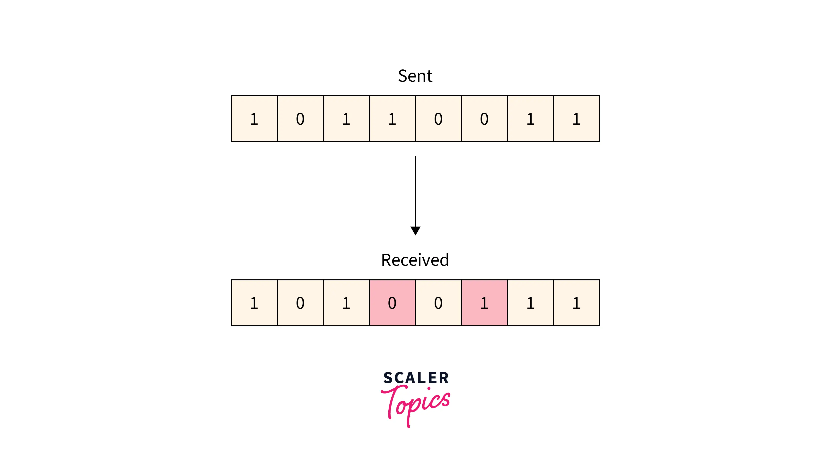
Multiple-bit Error
More than one bit received in the frame is found to be corrupted. Refer to the below image for the multiple-bit error
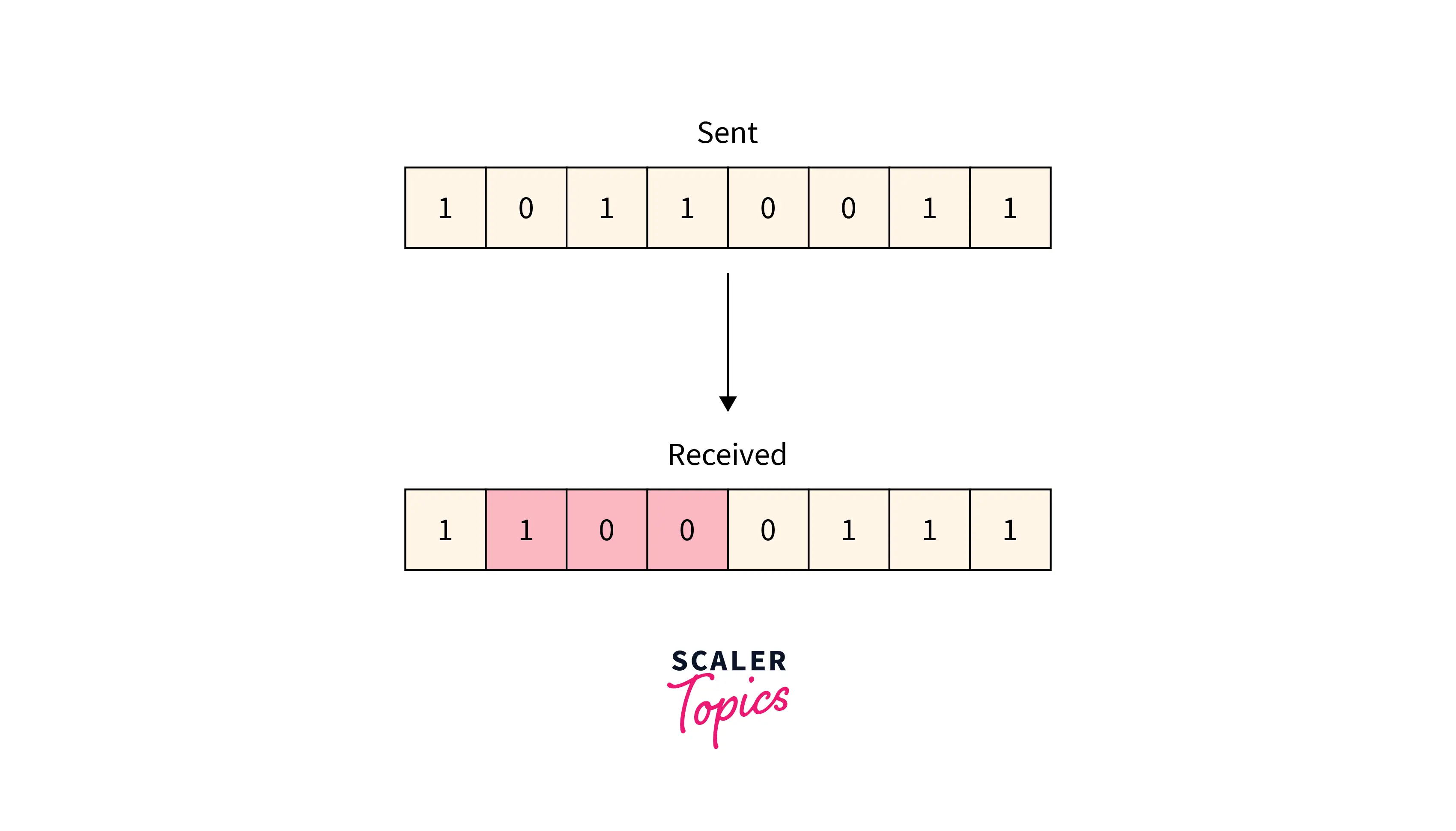
Burst Error
More than one consecutive bit is corrupted in the received frame.
Refer to the below image for the burst-bit error
Error Detection
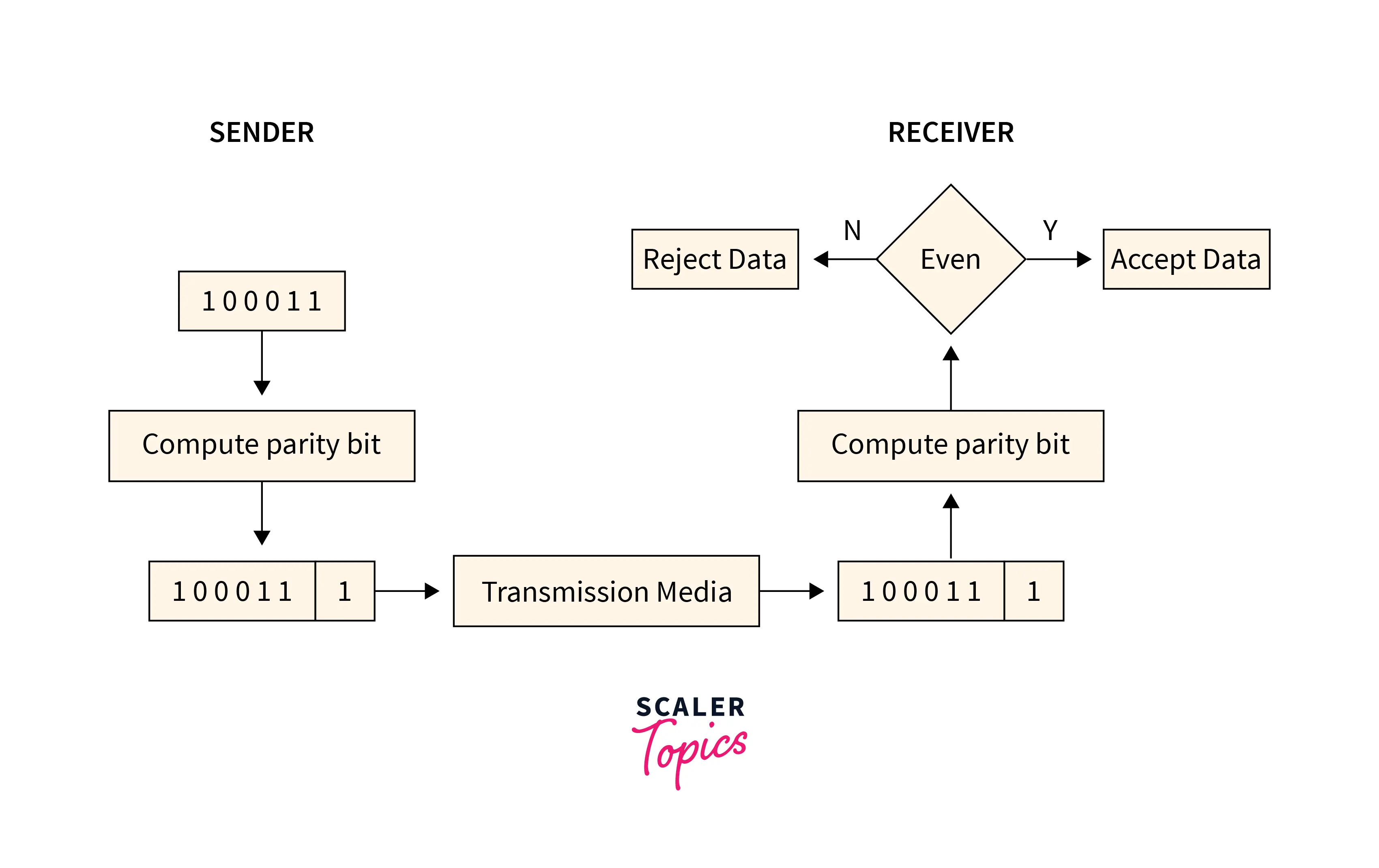
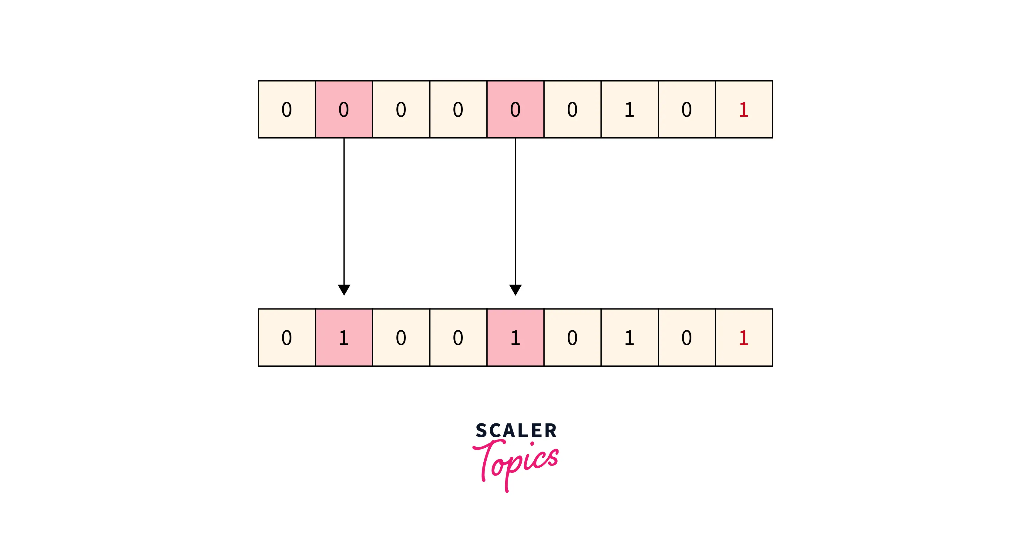
Simple Parity Check
Data sent from the sender undergoes parity check :
- 1 is added as a parity bit to the data block if the data block has an odd number of 1's.
- 0 is added as a parity bit to the data block if the data block has an even number of 1's.
This procedure is used for making the number of 1's even. This is commonly known as even parity checking.
Refer to the below image for the simple parity-checking method:
Disadvantage:
- Only single-bit error is detected by this method, it fails in multi-bit error detection.
- It can not detect an error in case of an error in two bits.
Refer to the below image for the disadvantage simple parity checking method
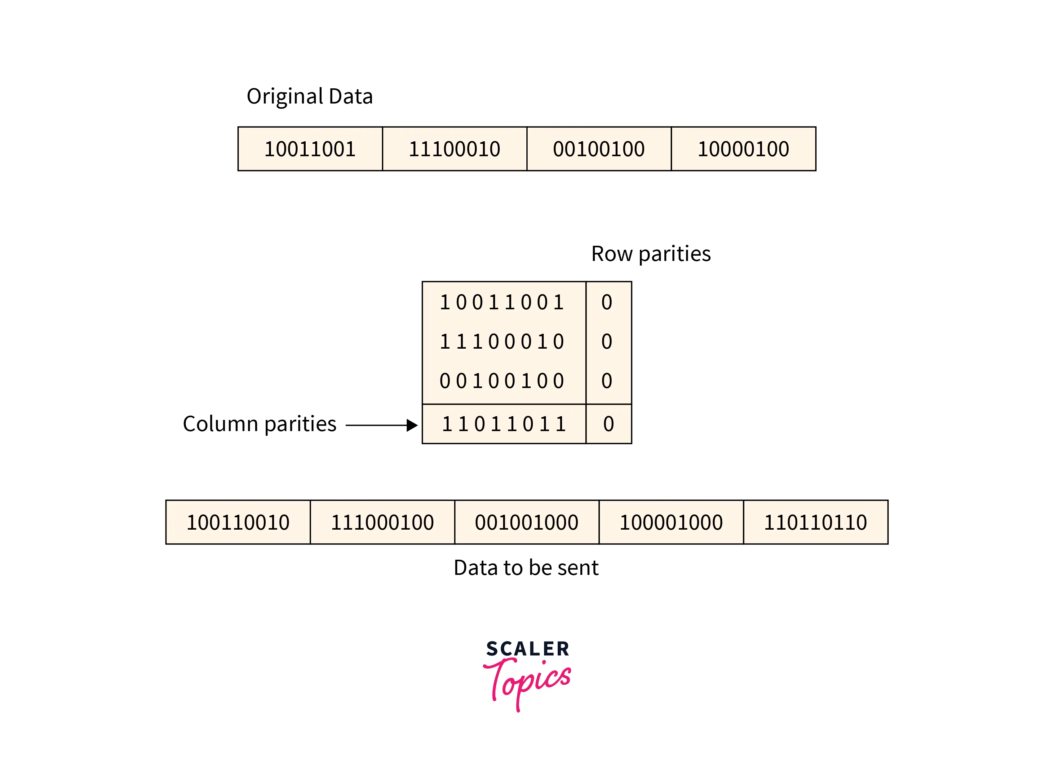
Two-Dimensional Parity Check
For every row and column, parity check bits are calculated by a simple method of parity check. Parity for both rows and columns is transmitted with the data sent from sender to receiver. At the receiver’s side, parity bits are compared with the calculated parity of the data received.
Refer to the below image for the two-dimensional parity checking method
Disadvantages:
- If 2 bits are corrupted in 1 data unit and another data unit exactly at the same position is corrupted then this method is not able to detect the error.
- Sometimes this method is not used for **detecting 4-bit **errors or more than 4-bit errors.
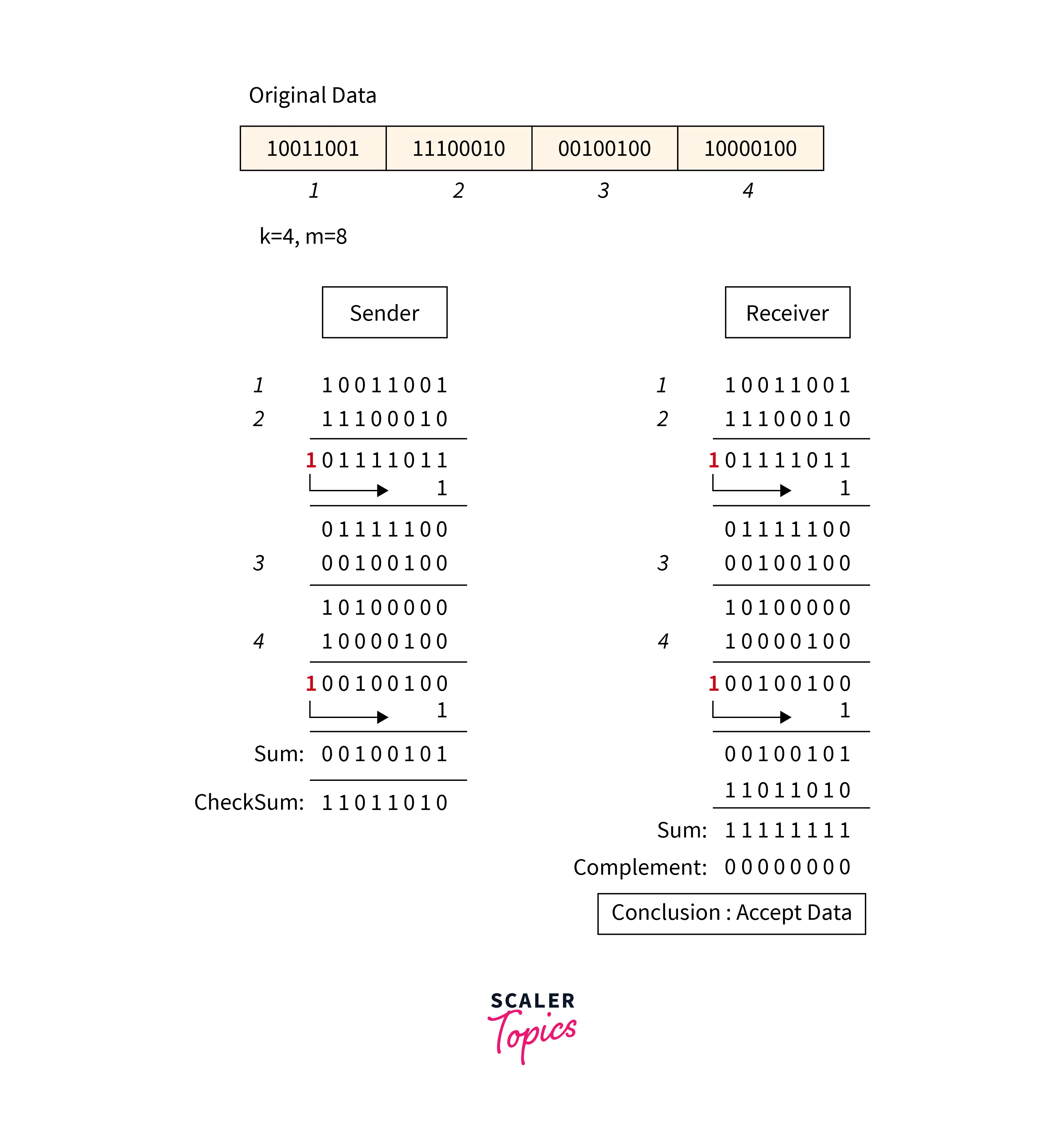
Checksum
Checksum is an error detection which detects the error by dividing the data into segments of equal size and then use 1's complement to find the sum of the segments and then the sum is transmitted with the data to the receiver and same process is done by the receiver and at the receiver side, all zeros in the sum indicates the correctness of the data.
- First of all data is divided into k segments in a checksum error detection scheme and each segment has m bits.
- For finding out the sum at the sender’s side, all segments are added through 1's complement arithmetic. And for determining the checksum we complement the sum.
- Along with data segments, the checksum segments are also transferred.
- All the segments that are received on the receiver's side are added through 1S complement arithmetic to determine the sum. Then complement the sum.
- The received data is accepted only on the condition that the result is found to be 0. And if the result is not 0 then it will be discarded.
Refer to the below image for the checksum method
Disadvantages: In checksum error is not detected, if one sub-unit of the data has one or more corrupted bits and corresponding bits of the opposite value are also corrupted in another sub-unit. Error is not detected in this situation because in this case the sum of columns is not affected by corrupted bits.
Turn Learning into Career Growth
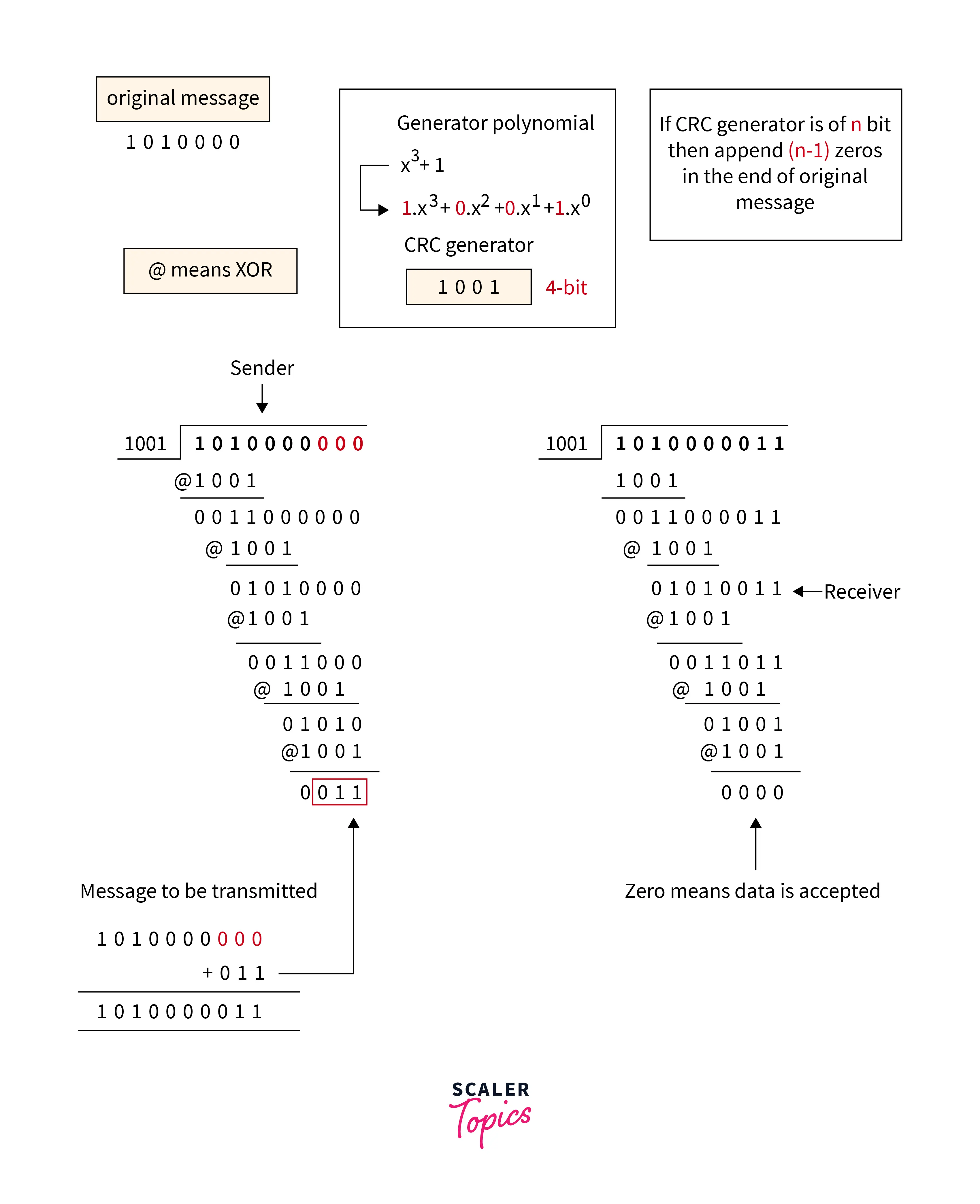
Cyclic Redundancy Check
Refer to the below image for the cyclic redundancy checking method
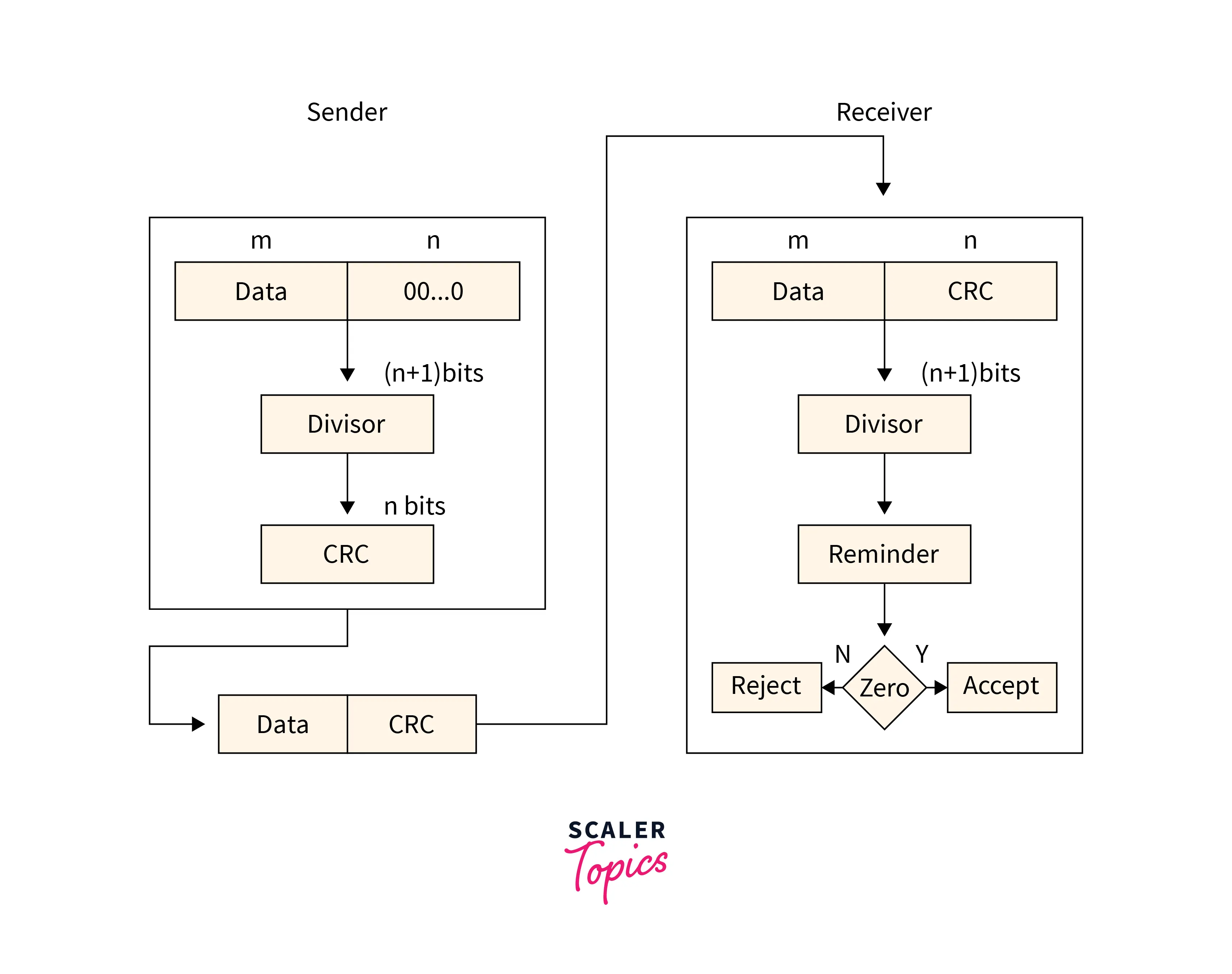
- The checksum scheme uses the addition method but CRC uses binary division.
- A bit sequence commonly known as cyclic redundancy check is added to the end of the bits in CRC. This is done so that the resulting data unit will be divisible by the second binary number that is predetermined.
- The receiving data units on the receiver's side need to be divided by the same number. These data units are accepted and found to be correct only on the condition that the remainder of this division is zero. The remainder shows that the data is not correct. So, they need to be discarded.
Refer to the below image for the example of the cyclic redundancy checking method
Disadvantages: Cyclic Redundancy Check may lead to overflow of data.
Error Correction
When the data is sent from the sender side to the receiver's side it needs to be detected and corrected. So an error correction method is used for this purpose. Following are the two ways through which error correction can be handled:
Backward Error Correction
In this method, When any error is found in the data at the receiver's end. Then the request for resending the whole data unit is sent by the receiver.
Forward Error Correction
In this method, an error-correcting code is used by the receiver that automatically corrects the errors.
Error Correction Techniques
We can detect the error using a single additional bit but we cannot use this bit for the correction purpose. It is important to know the exact location of the error if we want to correct that error. For example, for finding out the single-bit error, the error detection code checks out that the error is actually in one of the seven bits. Let d represents the number of data bits and r represents the number of redundant bits. The formula below is used for finding the r number of redundant bits :
The above formula is used to find out the value of r. For example, suppose 4 will be the value of d, then 3 will be the only and smallest value that satisfies this particular relation. A hamming code is a technique developed by R.W Hamming for finding out the position of the error bit. This Hamming code is based on the relationship between the redundant bits and data units and its main advantage is that it can be applied to data units of any length.
Hamming Code
Parity bits: The parity bits are the special type of bits that are added to the original data of binary bits to make the total 1s either even or odd.
Even parity: For checking the even parity, the following concept is used: The value of the even parity bit will be 0 if the total occurrence of 1s is even and the value of the parity bit can be 1 if the total occurrence of 1s is odd.
Odd Parity: For checking the even parity, the following concept is used: The value of the parity bit will be 1 if the total occurrence of 1s is even and the value of the parity bit can be 0 if the total occurrence of 1s is odd.
Algorithm of Hamming code:
- Add the information in 'd' bits to the redundant bits 'r' to make data as d+r.
- A decimal value will be assigned by the position of each (d+r) digit.
- In positions 1,2…2k, the 'r' bits will be placed.
- The parity bits are again calculated on the receiver's end. The position of an error defines the parity bit's decimal value.
Relationship b/w Error position & binary number:
| Error Position | Binary Number |
|---|---|
| 0 | 000 |
| 1 | 001 |
| 2 | 010 |
| 3 | 011 |
| 4 | 100 |
| 5 | 101 |
| 6 | 110 |
| 7 | 111 |
We take this example for a detailed explanation of the concept of hamming code. 1010 is supposed to be the original data that needs to be transferred.
'd' total number of data bits= 4 Redundant bits number=
So, the above-given relation is completely satisfied when 3 will be the value of r.
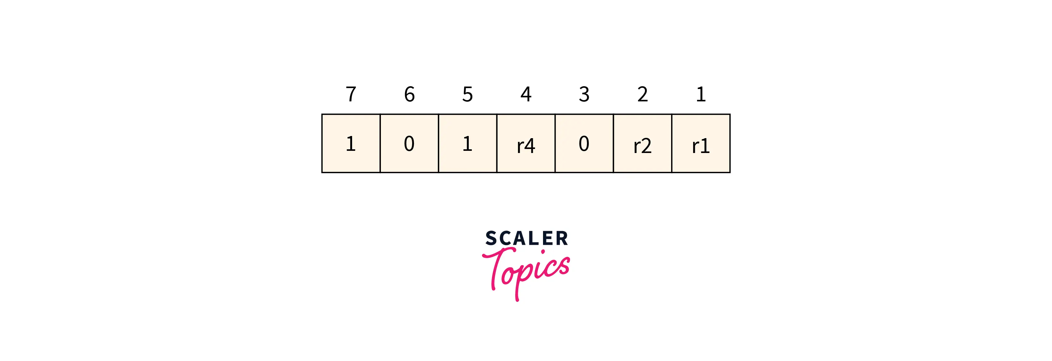
Determining the position of the redundant bits: 3 is the number of redundant bits. r1, r2, and r4 are used to show these three bits. We can find out the position of these bits for the raised power of 2. So according to this, their positions will be .
- r1 position is 1
- r2 position is 2
- r4 position is 4
Refer to the below image for the data with redundant bits
Determining the Parity Bits
Determining the r1 bit
The r1 bit value is calculated based on a parity check performed on the bits available at the position whose binary conversion contains 1 at the first position.
Refer to the below image for the finding r1 bit value
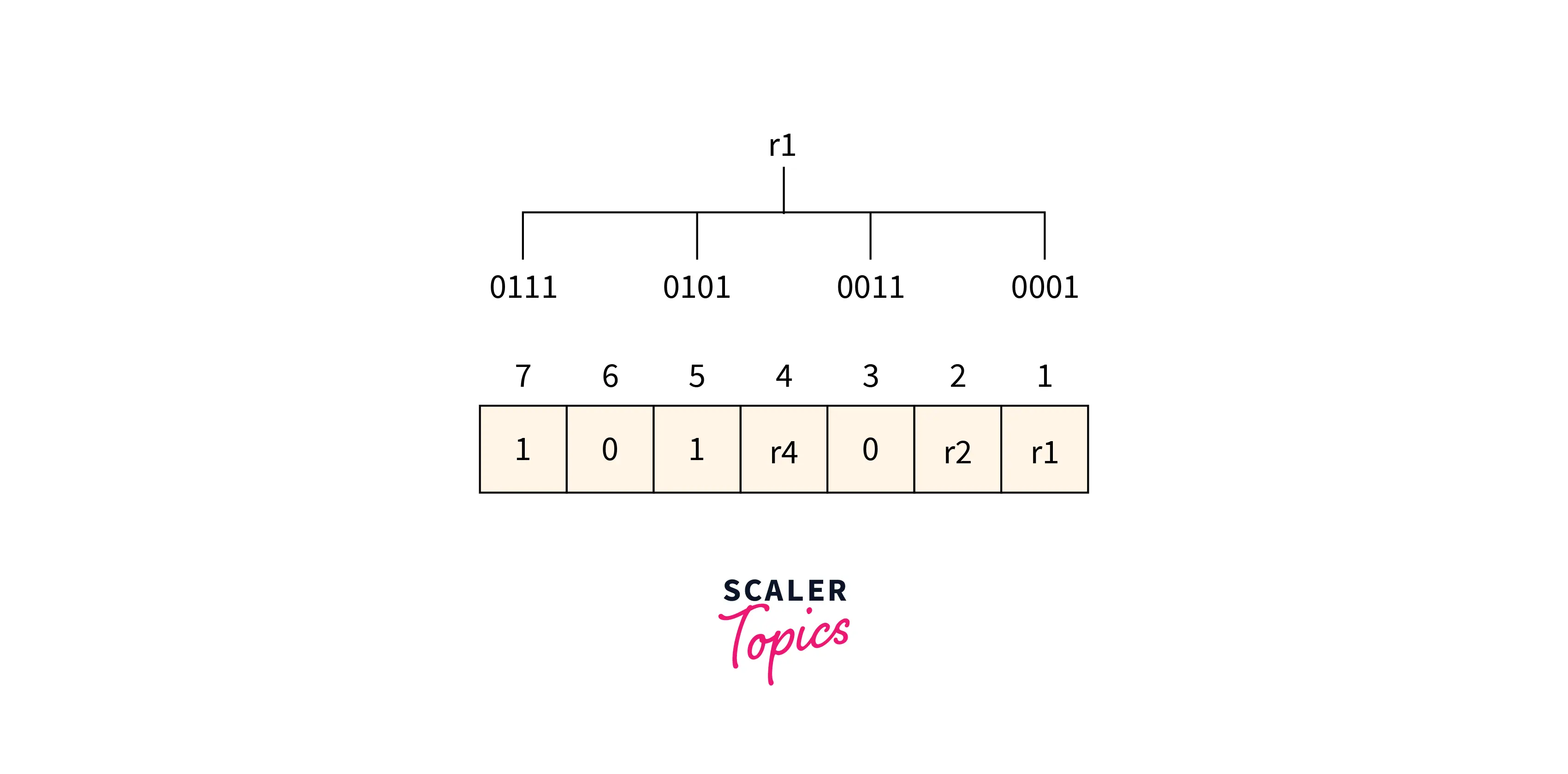
From the above figure, we can find the position having 1 as its first bit in binary representation is 1,3,5,6. Now the even-parity check method is applied to these bit positions. The number of 1’s at these bit positions 2 which is an even number so the 0 is the value of the r1 bit.
Determining r2 bit The r2 bit value is calculated based on a parity check performed on the bits available at the position whose binary conversion contains 1 at the second position.
Refer to the below image for the finding r2 bit value
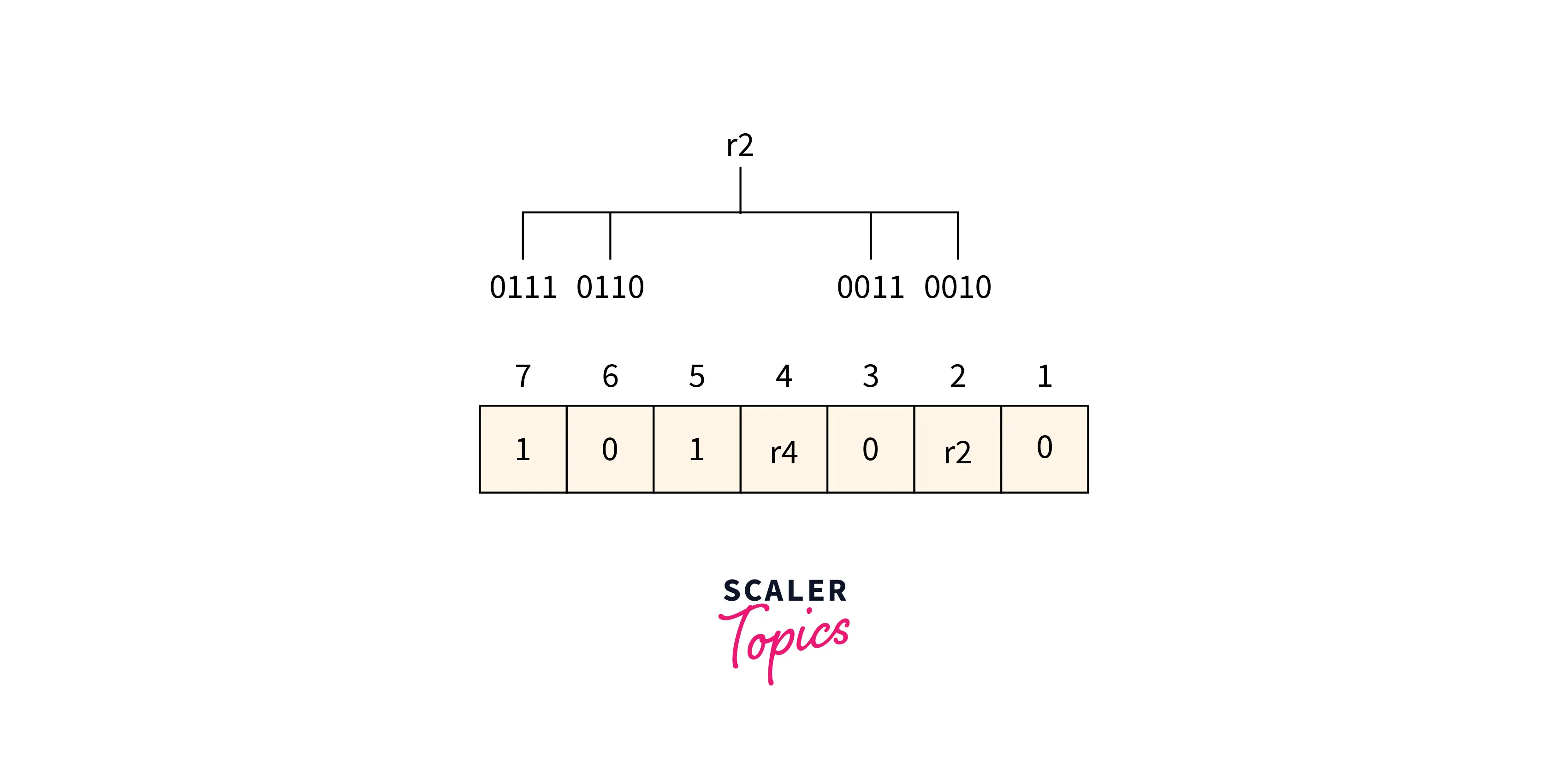
From the above figure, we can find the position having 1 as its second bit in binary representation is 2, 3, 6, 7. Now the even-parity check method is applied to these bit positions. The number of 1’s at these bit positions is 1 which is an odd number so 1 is the value of the r2 bit.
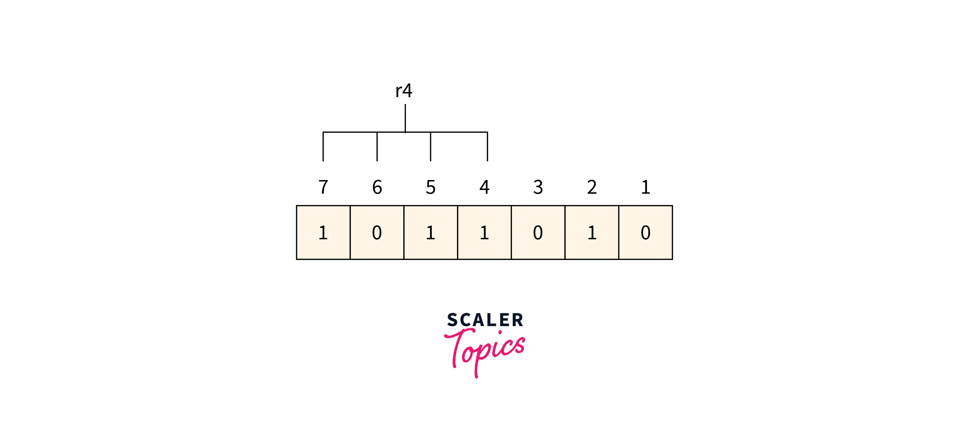
Determining r4 bit The r4 bit value is calculated based on a parity check performed on the bits available at the position whose binary conversion contains 1 at the third position.
Refer to the below image for the finding r4 bit value
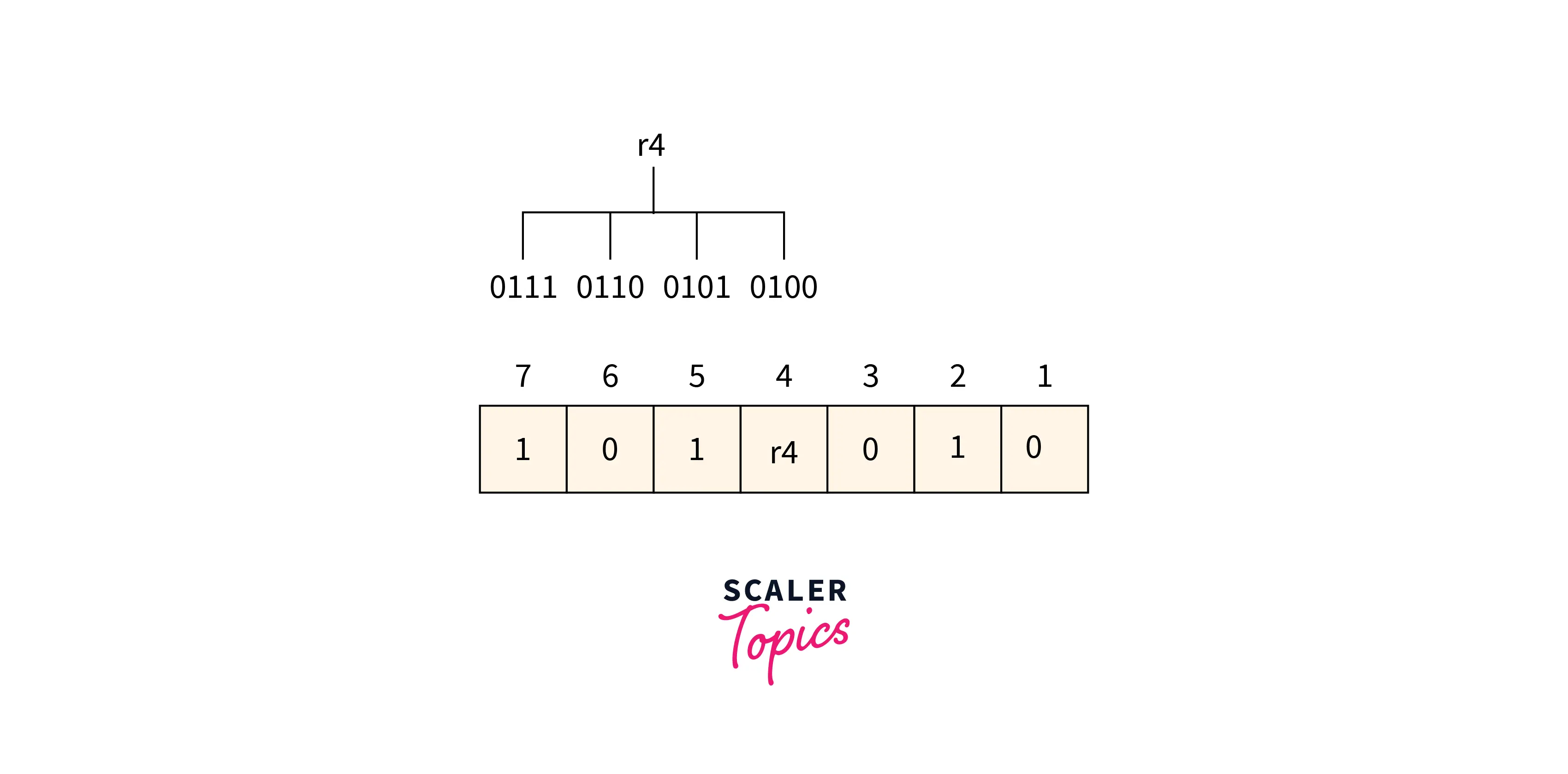
From the above figure, we can find the position having 1 as its third bit in binary representation is 4, 5, 6, 7. Now the even-parity check method is applied to these bit positions. The number of 1’s at these bit positions 2 which is an even number so the 0 is the value of the r4 bit.
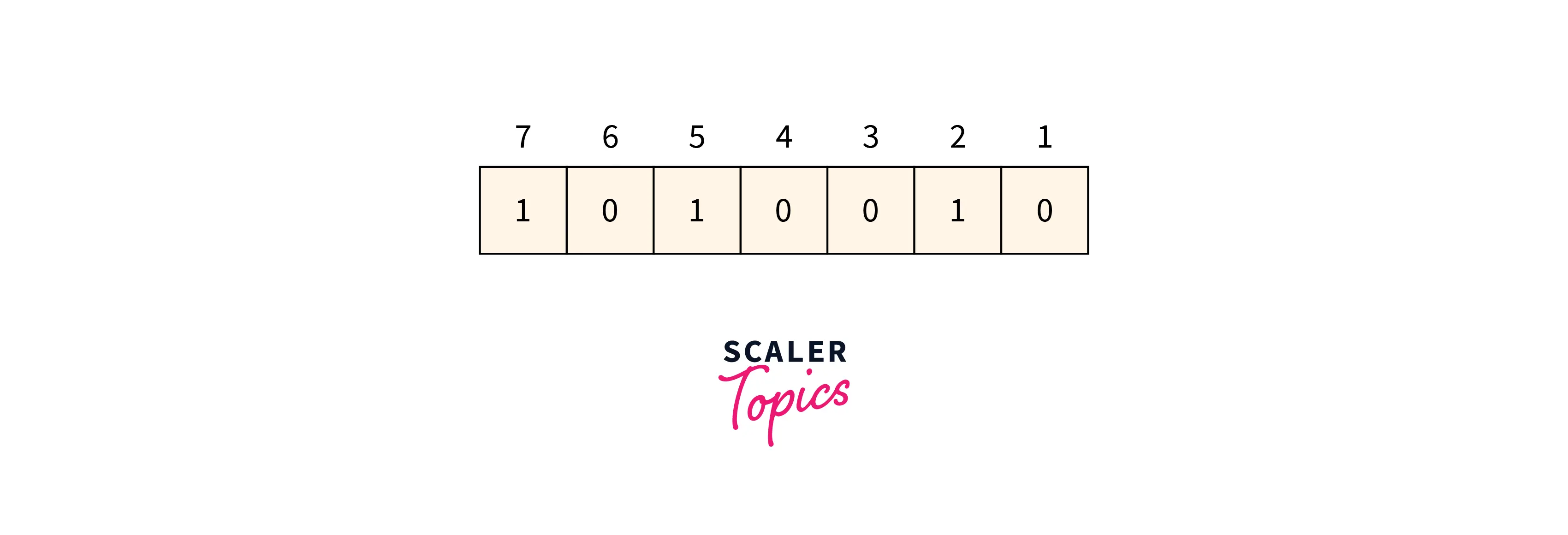
Data to be transmitted is given below:
Refer to the below image for the data to be transmitted.
Suppose when the data is received at the receiver end the value of the 4th bit is changed to 1 from 0. Now parity bits are calculated again to find the position of the error.
R1 bit 1, 3, 5 and 7 are the positions of the bits for the r1 bit.
Refer to the below image for calculating the r1 bit parity
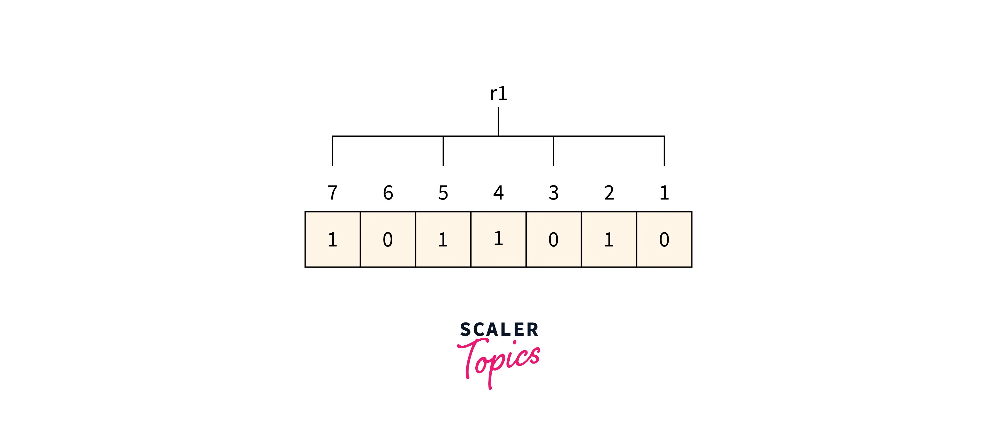
We can find from the above figure that the r1 binary representation is 1100. After applying the even-parity check method on the bits appearing in the r4 bits we get an even number of totals 1’s. So 0 is the value for the r1.
R2 bit 2, 3, 6, and 7 are the positions of the bits for the r2 bit.
Refer to the below image for calculating the r2 bit parity
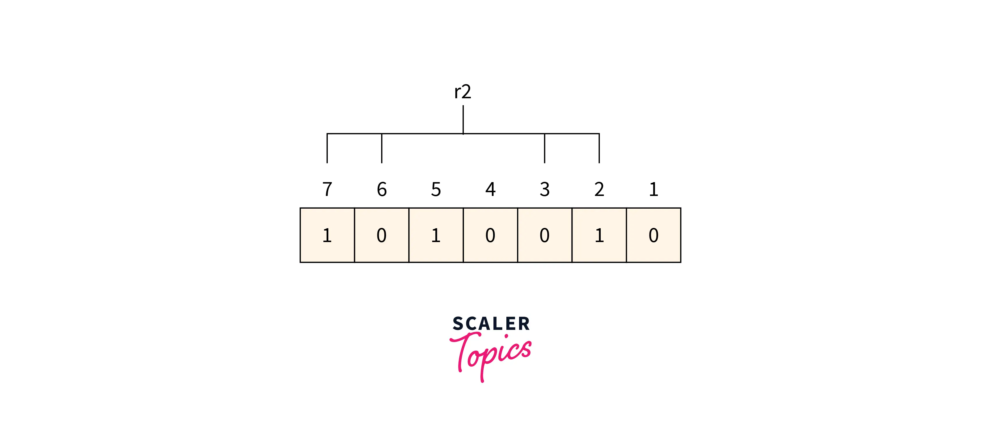
We can find from the above figure that the r2 binary representation is 1001. After applying the even-parity check method on the bits appearing in the r4 bits we get an even number of totals 1’s. So 0 is the value for the r2.
R4 bit 4, 5, 6 and 7 are the positions of the bits for the r4 bit.
Refer to the below image for calculating the r4-bit parity
We can find from the above figure that the r4 binary representation is 1011. After applying the even-parity check method on the bits appearing in the r4 bits we get an odd number of totals 1’s. So 1 is the value for the r4.
Redundant bits r4r2r1 binary representation is 100 which is represented as 4 in decimal value. So there is an error in the data at the 4th position and the value of the bit corresponding to the 4th position must be changed from 1 to 0 for error correction.
***Unleash your potential in the realm of computer networking. Enroll in our Free Computer Networking course and gain the knowledge to connect, secure, and optimize digital landscapes
Conclusion
- At the time of transmission, errors are introduced into the binary data sent from the sender to the receiver due to the noise during transmission.
- Single-bit error, multiple-bit error, and burst error are the types of error.
- Simple Parity check, Two-dimensional Parity check, Checksum, and Cyclic redundancy check are error detection methods.
- When the data is sent from the sender side to the receiver's side it needs to be detected and corrected. So an error correction method is used for this purpose.
- Backward and Forward are two Error Correction methods.
- Hamming Code is the technique used for error correction.