What is ER model in DBMS?

ER model in DBMS is the high-level data model. It stands for the Entity-relationship model and is used to represent a logical view of the system from a data perspective.
An ER diagram in DBMS defines entities, associated attributes, and relationships between entities. This helps visualize the logical structure of the database.

Component of ER Model in DBMS Diagram
The ER diagram consists of three basic concepts:
-
Entities
-
Attributes
-
Relationships

Transform Your Career
Choose from our industry-leading programs designed for career success
Modern Software and AI Engineering Program
Master full-stack development with AI integration

Modern Data Science and ML with specialisation in AI
Advanced data science techniques with AI specialization
Advanced AIML with Specialisation in Agentic AI
Deep dive into AIML with focus on Agentic systems
DevOps, Cloud & AI Platform Engineering
Build and manage AI-powered cloud infrastructure
AI Engineering Advanced Certification by IIT-Roorkee
Premier AI engineering certification from IIT-Roorkee
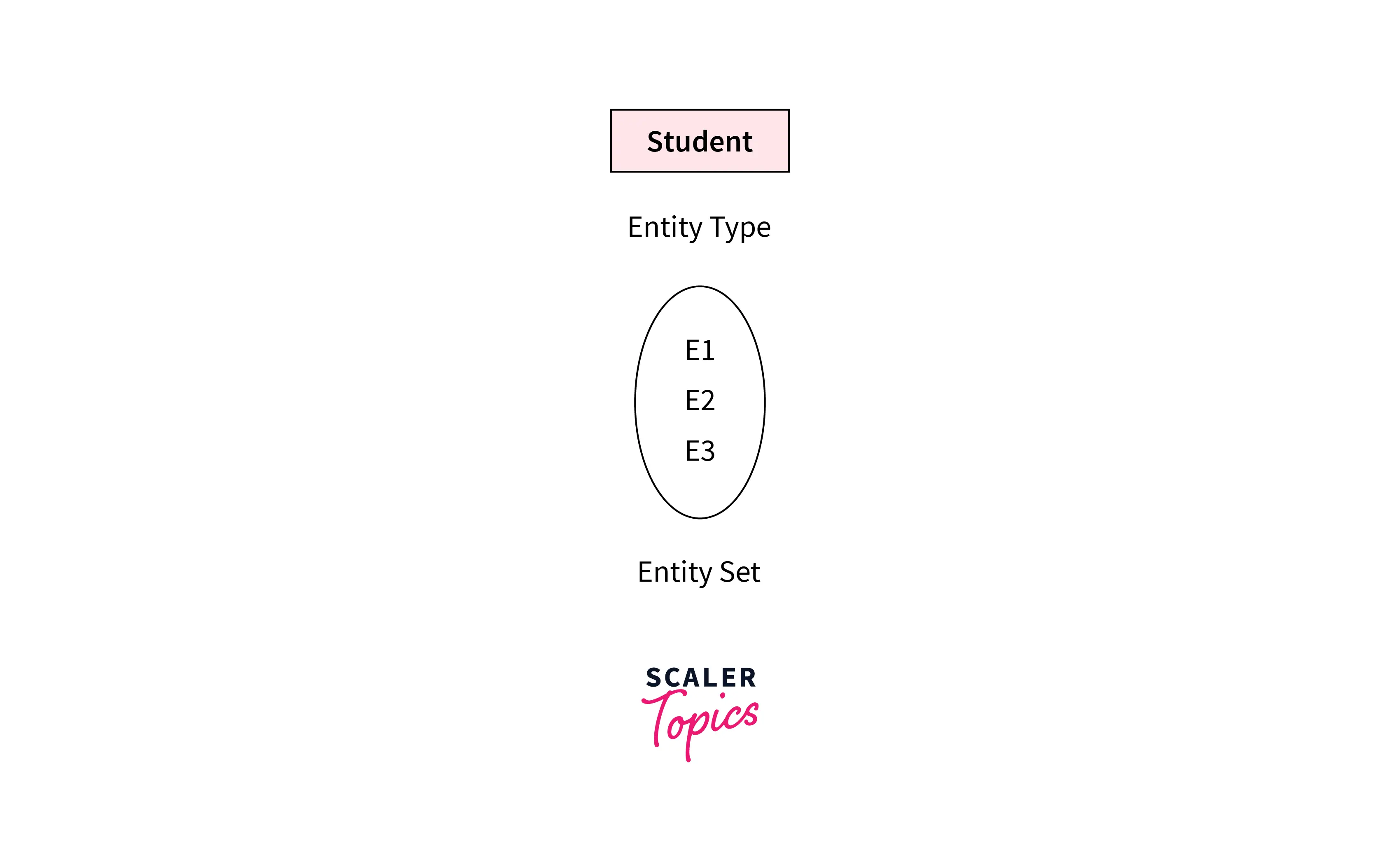
Entity Set
An entity is anything in the real world, such as an object, class, person, or place, and in DBMS it represents a real-world object in the database. Objects that physically exist and are logically constructed in the real world are called entities. Each entity consists of several characteristics or attributes that describe that entity. For example, if a person is an entity, its attributes or characteristics are age, name, height, weight, occupation, address, hobbies, and so on. Read this article to learn more about Entity in DBMS.
Entity set: is a group of entities of similar kinds. It can contain entities with attributes that share similar values. It's collectively a group of entities of a similar type. For example, a car entity set, an animal entity set, a bank account entity set, and so on.
Entity types: are the basic building blocks for describing the structure of data, making entities the main data entities used in data models, while the ER model works as a conceptual model of them. It's a category of a particular entity in an entity set. In summary, an Entity is an object of a Type Entity and the set of all entities is called an entity set.
Entities are of two types:
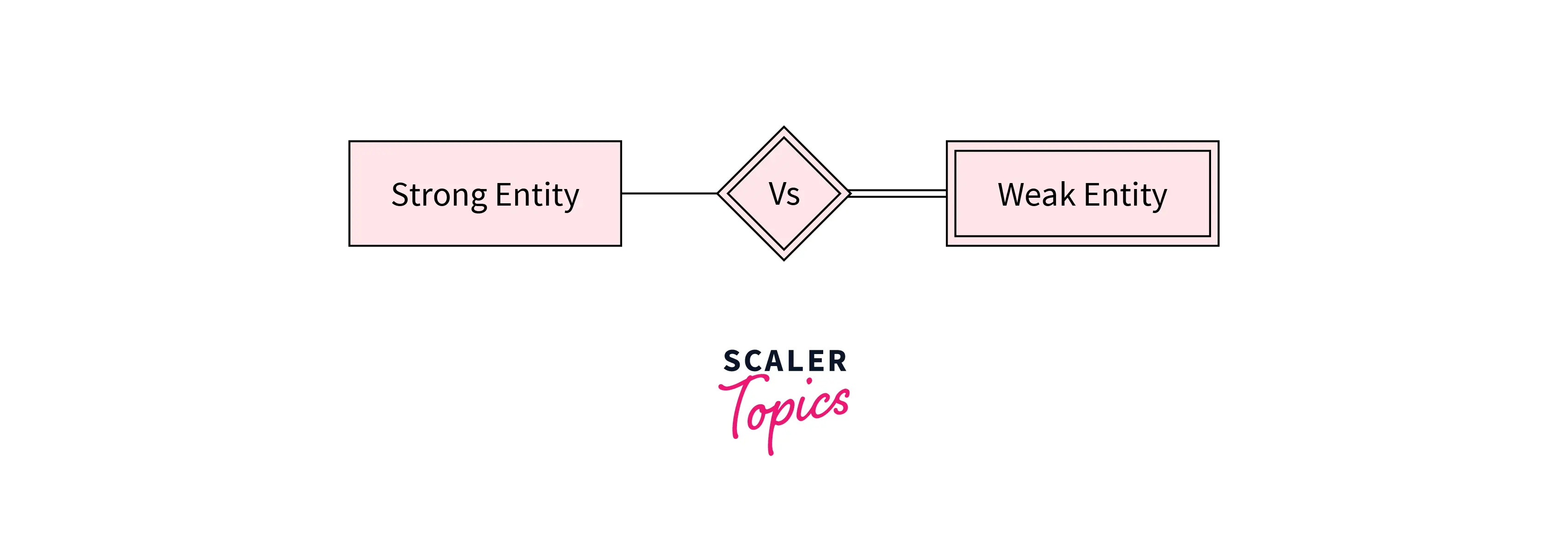
- Strong Entity – A strong entity is an entity type that has a key attribute and can be identified by its own attributes. It doesn't depend on other entities in the schema. A strong entity always has a primary key, and it is represented by a single rectangle in the ER diagram.
Example – roll_number identifies each student of the organization uniquely and hence, we can say that the student is a strong entity type. Similarly, a course entity in an ER diagram can be identified by a unique course_id.
- Weak Entity – Weak entity type doesn't have a key attribute and so we cannot uniquely identify them by their own attributes alone; unlike a candidate key, which is a minimal super key, it depends on a foreign key in combination with its attributes to create a primary key. They are called Weak entity types because they can't be identified on their own. It relies on another powerful entity for its unique identity. A weak entity is represented by a double-outlined rectangle in ER diagrams.
For example - the address can't be used to uniquely identify students as there can be many students from the same locality. So, for this, we need an attribute of Strong Entity Type i.e. 'student' to uniquely identify entities of Address Entity Type.
The relationship between a weak entity type and a strong entity type is shown with a double-outlined diamond instead of a single-outlined diamond. This representation can be seen in the image given below. Each entity in the set of strong entities can be uniquely identified because it has a primary key, whereas identifying each entity in a set of weak entities is not possible. After all, it has no primary key and it may contain redundant entities.
Key Attribute
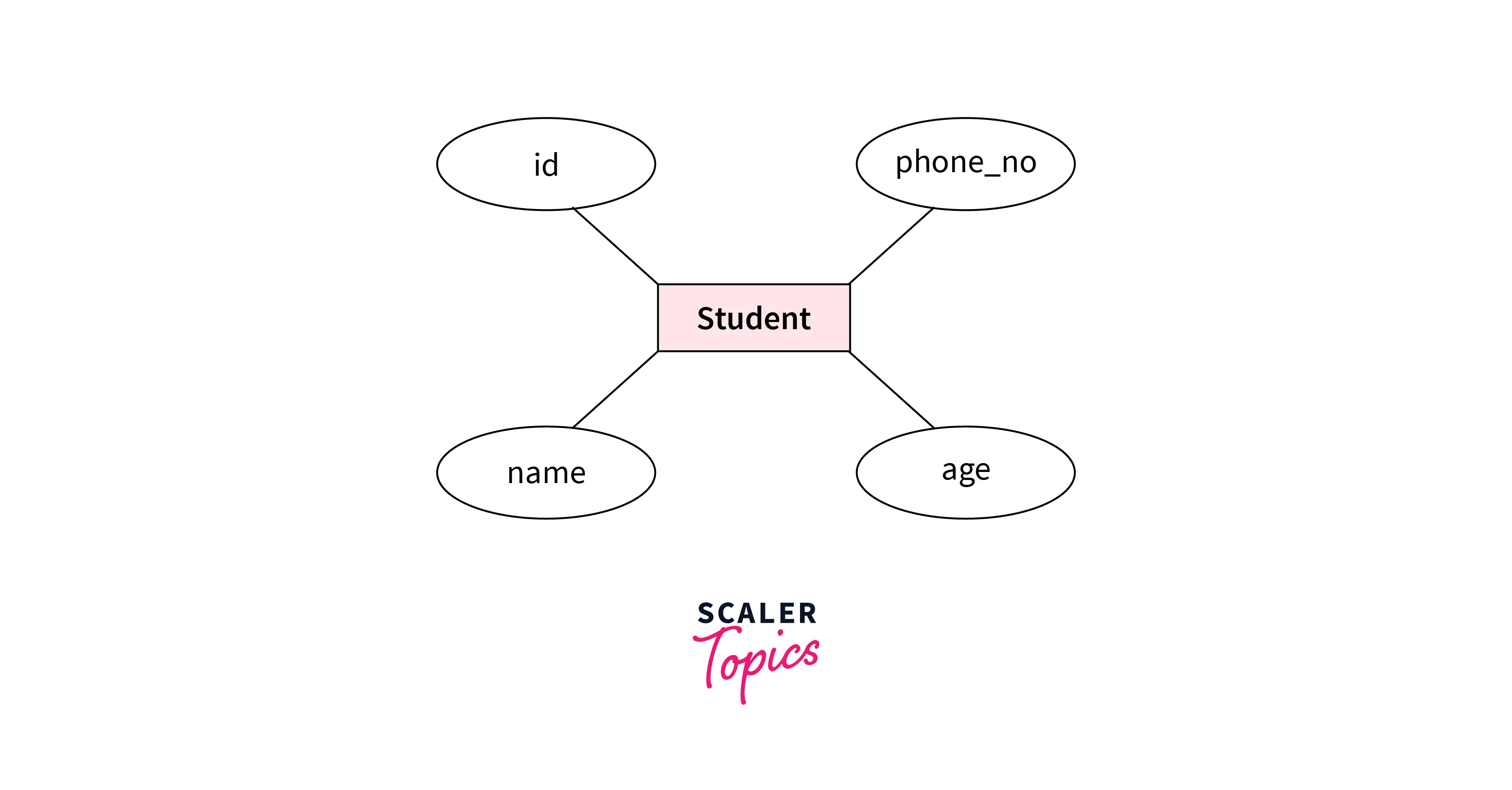
Attributes are the characteristics or properties that define the entity type, and they act as data elements used to describe entities in structured data. In the ER diagram, the attribute is represented by an oval.
For example, here id, Name, Age, and Mobile_No are the attributes that define the entity type Student and provide a visual representation of data structures in the ER diagram.
There are five types of attributes:
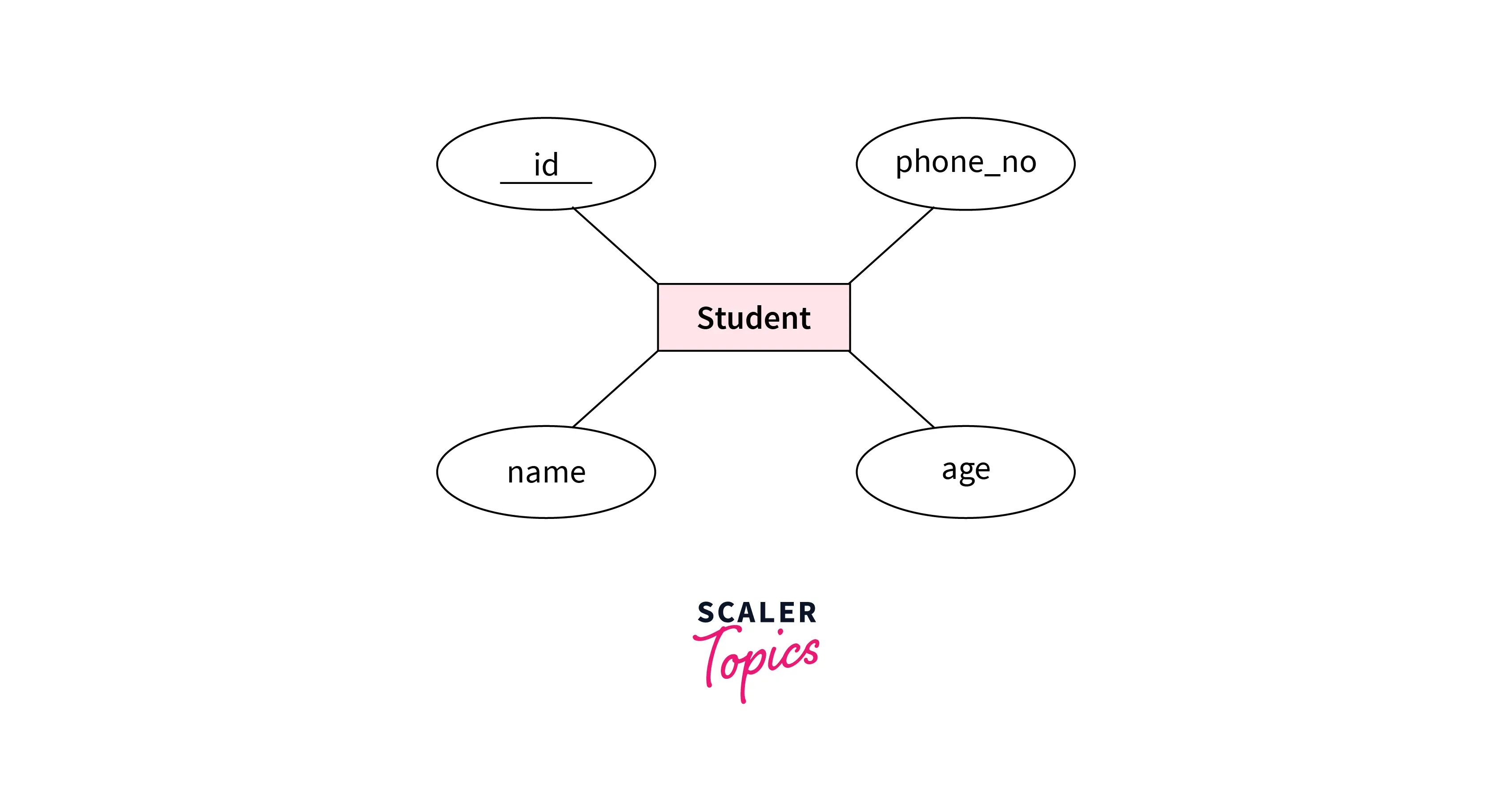
- Simple attribute: Attributes that cannot be further decomposed into sub-attributes are called simple attributes. It's an atomic value and is also known as the key attribute. The simple attributes are represented by an oval shape in ER diagrams with the attribute name underlined.
For example, the roll number of a student, or the student's contact number are examples of simple attributes. As you can see from the above image, the attributes id is represented in the shape of an ellipse along with having the attribute name underlined.
- Composite attribute: An attribute that is composed of many other attributes and can be decomposed into simple attributes is known as a composite attribute in DBMS. The composite attribute is represented by an ellipse.
For example, a student's address can be divided into city, state, country, and pin code or a full name can be divided into first name, middle name, and last name.
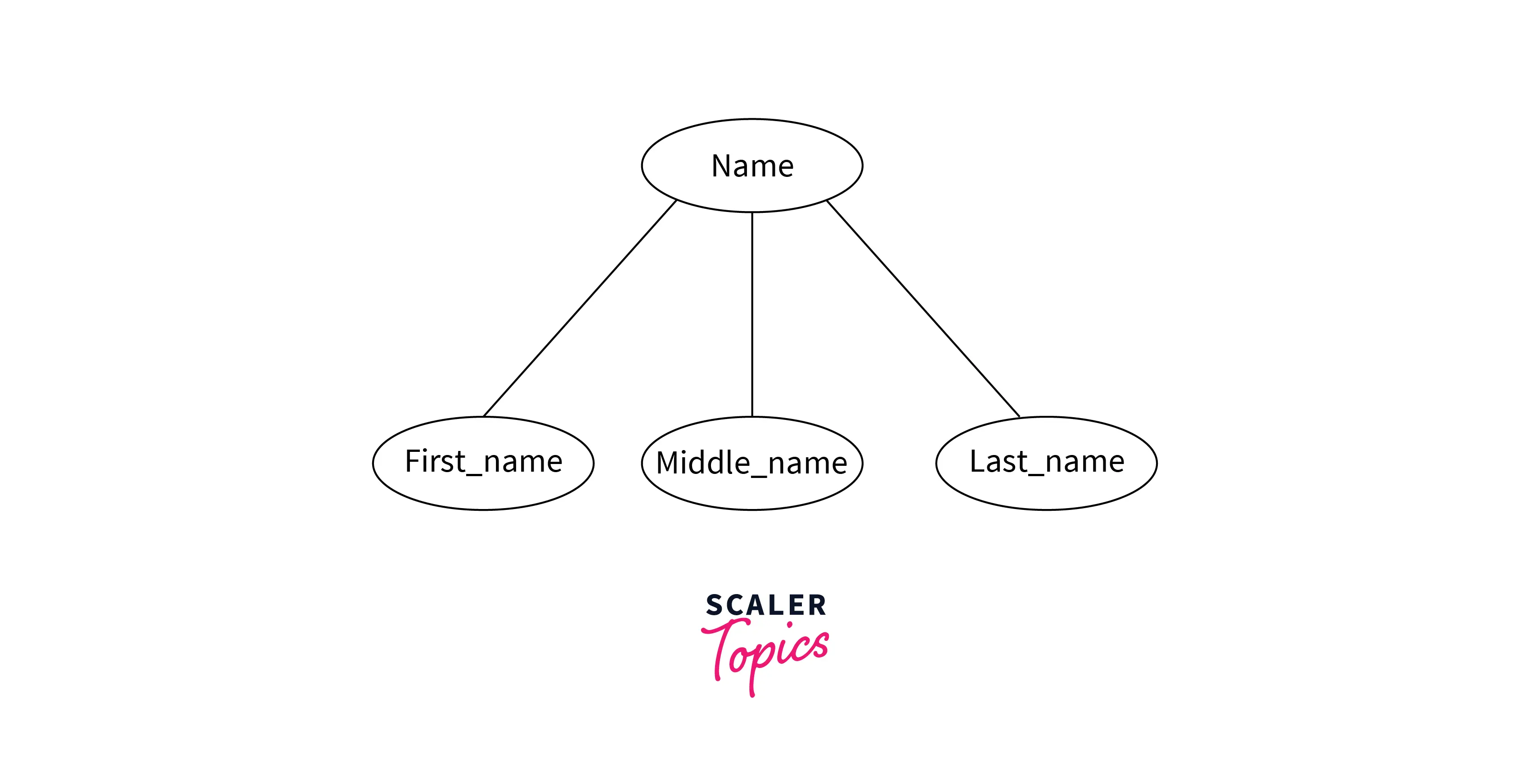
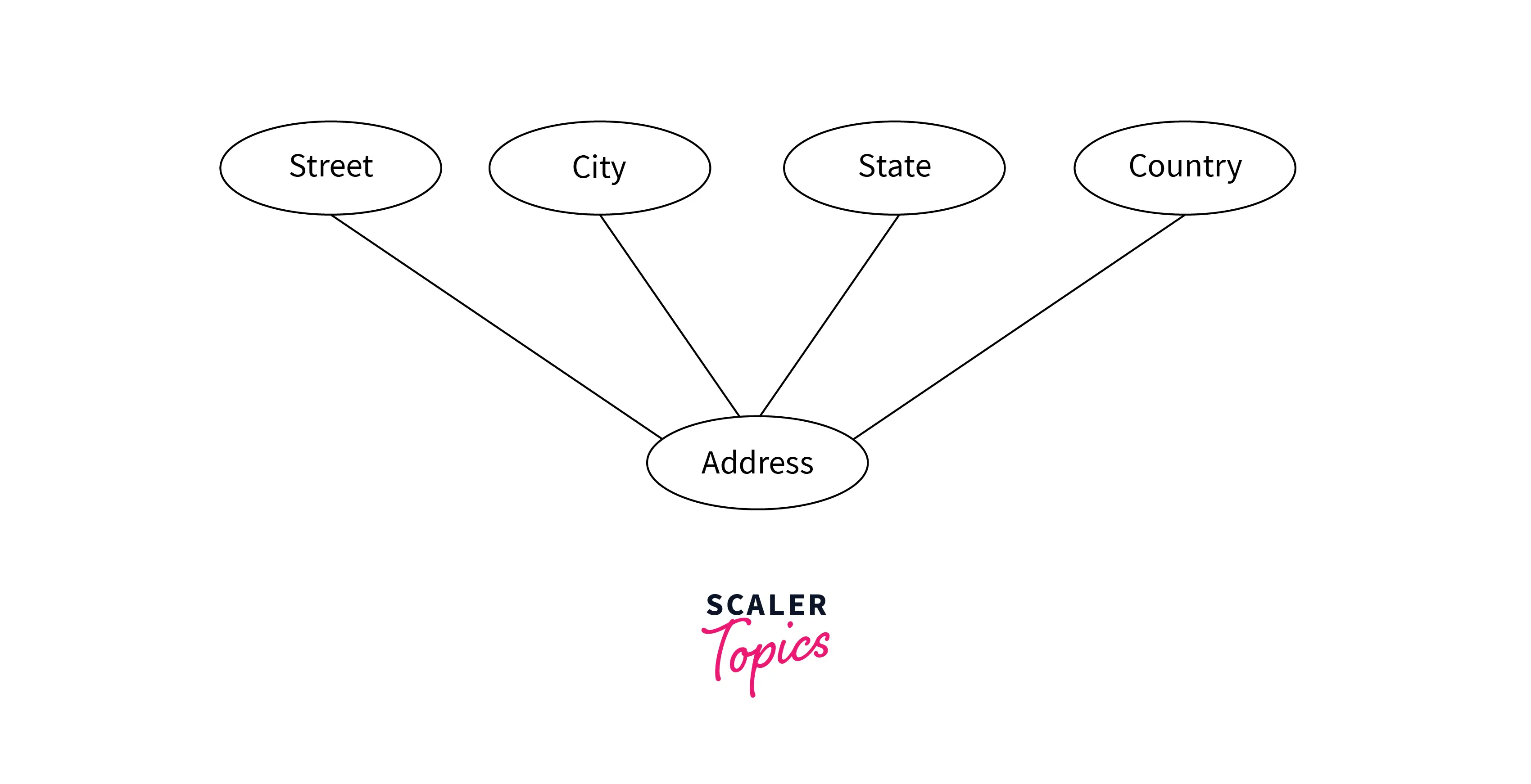 As you can see from the above images, the composite attribute is divided into multiple simpler attributes.
- Multivalued attribute: Multivalued attributes in DBMS are attributes that can have more than one value. The double oval is used to represent a multivalued attribute.
For example, the mobile_number of a student is a multivalued attribute as one student can have more than one mobile number.

- Derived attribute: Derived attributes in DBMS are the ones that can be derived from other attributes of an entity type. The derived attributes are represented by a dashed oval symbol in the ER diagram.
For example, the age attribute can be derived from the date of birth (DOB) attribute. So, it's a derived attribute.
 The complete student (represented by the rectangle shape) entity type is shown by the below diagram having different attributes, where address is the composite attribute, age is the derived attribute, phone number is the multivalued attribute, and roll number is the key attribute. Check out this article to learn more about types of attributes in DBMS.
(https://scaler.com/topics/images/complete-student-entity-type-having-different-types-of-attributes.webp)
The complete student (represented by the rectangle shape) entity type is shown by the below diagram having different attributes, where address is the composite attribute, age is the derived attribute, phone number is the multivalued attribute, and roll number is the key attribute. Check out this article to learn more about types of attributes in DBMS.
(https://scaler.com/topics/images/complete-student-entity-type-having-different-types-of-attributes.webp)
Relationship Type
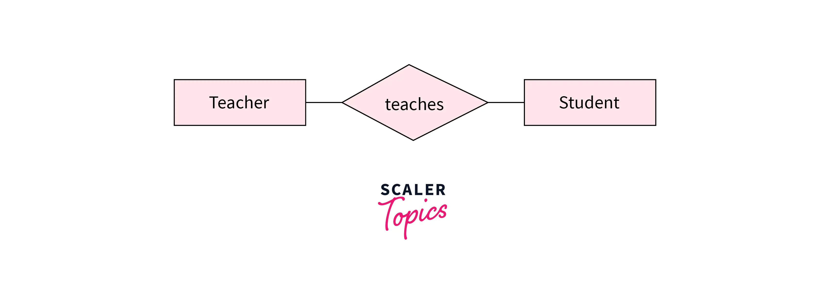
The concept of relationship in DBMS is used to explain how entities are connected in an entity-relationship diagram, and these links are shown with connecting lines and a diamond or rhombus symbol. For example, the teacher entity type is related to the student entity type and their relation is represented by the diamond shape. A relationship type describes this association, while all such associations together form a relationship set.
There are four types of relationships based on relationship cardinality and cardinality constraints:
-
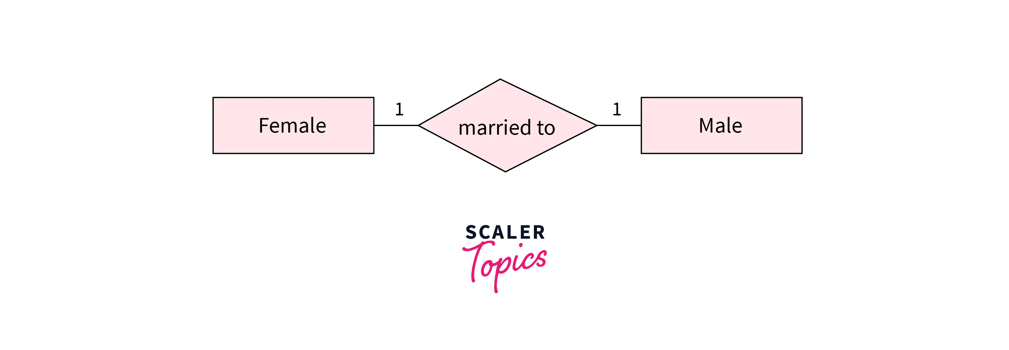
One-to-One Relationships: When only one instance of an entity is associated with the relationship to one instance of another entity, then it is known as one to one relationship. Here, one entity can be associated with one or many instances depending on the participation constraint. For example, let us assume that a male can marry one female and a female can marry one male. Therefore the relation is one-to-one.
-
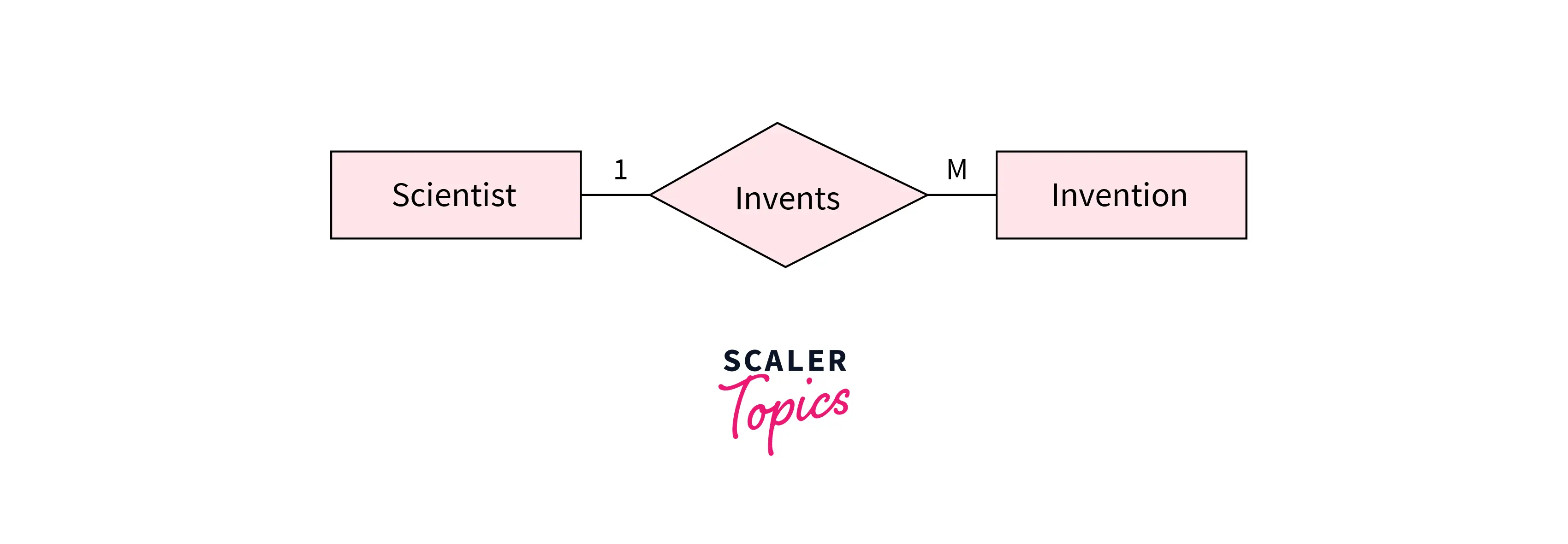
One-to-Many Relationships: If only one instance of the entity on the left side of the relationship is linked to multiple instances of the entity on the right side, then this is considered a given one-to-many relationship. For example, a Scientist can invent many inventions, but the invention is done by only a specific scientist.
-
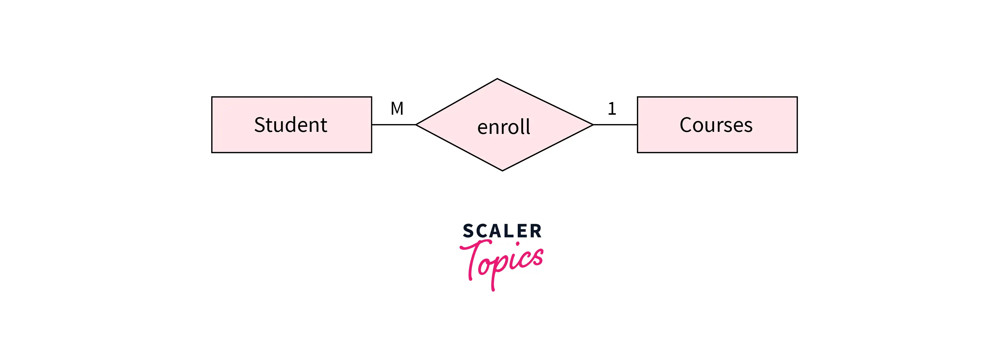
Many-to-One Relationships: If only one instance of the entity on the left side of the relationship is linked to multiple instances of the entity on the right side, then this is considered a given one-to-many relationship. For example, a Student enrolls for only one course, but a course can have many students.
-
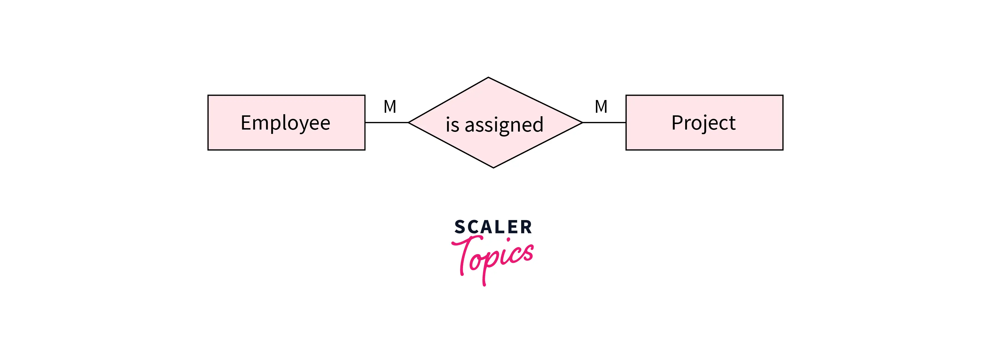
Many to Many Relationships: If multiple instances of the entity on the left are linked by relationships to multiple instances of the entity on the right, this is considered a many-to-one-relationship means relationship. For example, one employee can be assigned many projects, and one project can be assigned by many employees.
An entity set participates in a relationship with either total or partial participation.
Features of ER
The features of the ER Model are as follows −
-
ER Diagram: ER diagrams are the diagrams that are sketched out to design the database. An entity relationship diagram is a visual representation and a visual tool for representing entities and relationships in relational database design, helping database designers, business analysts, and project managers understand data structures and the relationships between data elements. They are created based on three basic concepts: data entities, attributes, and relationships between them. In ER diagram we define the entities, their related attributes, and the relationships between them. This helps in illustrating the logical structure of the databases.
-
Database Design: The entity relationship model adopts a high-level view of the real world consists of objects and links, and helps database designers build the database as a conceptual model before moving to logical and physical model stages.
-
Graphical Representation helps in Better Understanding: ER diagrams are very easy and simple to understand, so developers can use them to communicate with stakeholders in software engineering use cases. Ideas about representing interconnectedness long predate ER modeling, tracing back to ancient Greece and later formal logic.
-
Easy to build: The ER model is very easy to build.
-
The extended E-R features: Some of the additional features of ER model are specialization, upper and lower-level entity sets, attribute inheritance, aggregation, and generalization.
-
Integration of ER model: This model can be integrated into a common dominant relational model, supporting transition toward physical implementations and alignment with a relational database, and is widely used by database designers for communicating their ideas. ER tools can also work with existing databases through reverse-engineering or synchronization so documentation stays aligned with current systems.
-
Simplicity and various applications of ER model: It provides a preview of how all your tables should connect, what fields are going to be on each table, and how data models map underlying data structures, which can be used as a blueprint for implementing data in specific software applications.
Scaler Placement Report and Statistics
Scaler learners achieved 2.5x salary growth with average post-Scaler CTC reaching ₹23L.
Learn More:
Conclusion
-
The ER diagram was developed by Peter Chen in the 1970s as a visual tool to represent the ER model, and he published the 1976 paper "The Entity-Relationship Model: Toward a Unified View of Data."
-
ER model stands for Entity relationship model and is a high-level conceptual model used to represent the system from a data perspective before logical design and physical implementations.
-
ER diagrams are created based on three basic concepts: entities, attributes, and relationships between them, serving as a visual representation of entities and relationships in relational database design.
-
Strong entities are those entity types that have a key attribute, whereas weak entity types don't have a key attribute and so we cannot uniquely identify them by their attributes alone.
-
Attributes are the characteristics or properties that define the entity type.
-
Relationship defines how two or more entities are connected within the database system.
-
Some ER-based query approaches, such as ERROL, draw on reshaped relational algebra to query ER models in a more natural-language-like way.